Network Scopes
This view allows creating Multicast Network Scopes.
A Network Scope represents a single network. It may span across multiple switches in the actual physical topology, but connectivity between hosts assigned to the same network scope is assumed. While in theory IP routing may be set up between Network Scopes on the switch fabric itself, we assume that high-bandwidth media traffic will not leave the Network Scope it belongs to by default. In a later step network control functionalities might be added which will enable this traffic to flow between Network Scopes in a controlled way (e.g. to create separated islands and granularily control traffic moving between them).
Overview
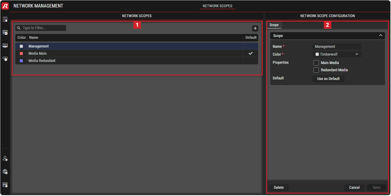
Network Management - Network Scopes
 Network Scopes
 | Filter to display only content whose search text is found in the Name (case insensitive). |
|---|---|
 | Button to add a network to the STAGE system. |
 | Button to change the order of the displayed networks. |
Color | Displays the color of this net for easy identification. |
Name | Name of the network. |
Default | Indicates the default network in the STAGE system. |
 Network Scope Configuration
Name | Name of the network. |
|---|---|
Color | Color of the network. |
Properties | Checkboxes to set the network as the Main or Redundant Media network. |
Default | Button to set this network as the default. |
Using the Network Management view
Adding a Network
In the NETWORK SCOPES section, click on the
 button.
The NETWORK SCOPE CONFIGURATION section is expanded on the right.In the NETWORK SCOPE CONFIGURATION section, open the Scope tab if not already shown.
Enter the Name for the new network.
Choose a color for the new network.
Define if the network is used to transport Main or Redundant Media data.
Optional: Set this network as your default network.
Click on the
 button to add the network.
Changing Network Information
In the NETWORK SCOPES section, select the network whose information are to be changed.
In the NETWORK SCOPE CONFIGURATION section, open the Scope tab if not already shown.
Change the information according your requirements.
Click on the
 button to apply the changes.
Adding a Multicast Configuration
In the NETWORK SCOPES section, select the network whose IP settings are to be set/changed.
In the NETWORK SCOPE CONFIGURATION section, open the Multicast Configuration tab if not already shown.
To enter information about Multicast Ranges or Reserved Addresses,
click on the button in the corresponding section.
In the dialog that opens, enter the information as required.
Changing a Multicast Configuration
In the NETWORK SCOPES section, select the network whose IP settings are to be changed.
In the NETWORK SCOPE CONFIGURATION section, open the Multicast Configuration tab if not already shown.
Select the stream whose multicast configuration is to be changed.
Click on the
 button to open a dialog for entering stream information.
Enter the Name for the stream.
Define if the essence type (Video, Audio, Ancillary).
Enter the IP range (Start IP and End IP).
Enter the port.
Click on the Create button.

