
StageLink supports the Open Sound Control (OSC), which is a network-based protocol for real-time control of multimedia applications. As a flexible successor to MIDI, it uses a URL-like addressing structure and is typically based on UDP, which enables precise, bidirectional communication of parameters such as volumes.
This means that the GPIs of StageLink devices can send specific parameters to other OSC-compatible devices. And vice versa, external devices can send commands to StageLink devices to control their GPOs.
Steps to enable OSC on StageLink devices
-
Open the Web Interface of the desired StageLink device.
-
In the Device Settings tab, activate
OSC (Media X). -
If required, change the
Port(default: 8000). -
Select the transport Protocol (
TCP,UDP,TCP & UDP).
If UDP is selected,Use Multicastcan be enabled. -
On the Network Settings tab, select the interface through which OSC data is to be transmitted.
Command Syntax to control StageLink GPOs
To set the GPO of a StageLink device, the following argument must be received from a controlling device:
-
To activate the NSA's GPOutput:
/gpo/xxx/activateor/gpo/xxx/value T -
To deactivate the NSA’s GPOutput:
/gpo/xxx/deactivateor/gpo/xxx/value F
The ID xxx in the example above refers to the device's GPO port and must be replaced with the desired GPO number, such as 003.
If the ID contains the asterisk wildcard, such as 00*, 0**, or *, all corresponding GPOs of the device will be changed simultaneously.
All characters must be lowercase, and there must be no spaces at the end of the line.
Command Syntax to control a remote OSC client via GPIs
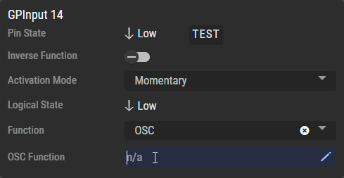
First, set the GPI's Function combo box to OSC to activate the text field and the pen.
Click on the ![]()
In the Pop-up dialog enter the following information:
|
Active Path |
Describes the function being send when the GPI changes to |
|---|---|
|
Inactive Path |
Describes the function being send when GPI changes to |
|
IP Address |
Set the destination IP-Address (or Multicast Group). |
|
Port |
Set the destination Port number. |
|
Transport Mode |
Set according to the settings on the destination device. |
Your entries will be saved automatically when you close this dialog box.
Path Structure (for Active/Inactive Path)
The general syntax of the OSC string to be transmitted for activating/deactivating is as follows:
address variable definition argument [1...n], e.g.: /remote/gpi1 TifsF 165 3.54 hello.
|
Address |
Specifies the address of your destination device, e.g. |
|
|---|---|---|
|
Variable Definition |
Specifies the types (and quantity) of variables to be transmitted, e.g. |
|
|
Boolean |
|
|
|
Integer |
|
|
|
Float |
|
|
|
String |
|
|
|
Optional Argument(s) |
Arguments to be transmitted to your destination device, e.g. |
|
In this example, the destination device receives the following log:
ADDRESS(/remote/gpi1) BOOL(TRUE) INT32(165) FLOAT(3.54) STRING(hello) BOOL(FALSE)
The entries must be separated by a space. There must be no spaces at the end of the line.
You can enter all the information directly into the OSC Function field on a single line using the following syntax:
Active Path|Inactive Path|IP Address:Port|Transport Mode
The NSA can also be discovered via mDNS as an OSC-enabled device.