
Introduction
The SAME DSP Engine Host Configuration has a Direct Control Mode that:
-
Exposes static senders and receivers to external systems using AMWA NMOS IS-04 and IS-05.
-
Registered Device’s audio signals.
-
Processing Plugins and Mixers audio signals.
-
-
Provides parametric control and operational User Interfaces for processing Plugins and Mixers through the STAGE northbound GRPC Northbound API. See STAGE Northbound API for more information about this API.
-
Through this API, the URLs for plugins and mixer Web interfaces are available, allowing you to integrate these screens into your Broadcast Control System (BCS).
-
The SAME DSP Engine uses the STAGE Northbound API to receive control commands and to send status updates.
-
For example, a SAME DSP Engine can be used in a static way to provide plain processing resources to an environment managed by a BCS and/or SDN. If parametric control from a BCS is required, the BCS must implement the STAGE GRPC Northbound API accordingly.
When the SAME DSP Engine is in Direct Control Mode:
-
It does not support a user being able to run Jobs and configure Volumes. It is dedicated to being operated by the BCS only.
-
The SAME DSP Engine and integrated Riedel Devices are not added or configured to the BCS directly. Instead they are discovered in STAGE using proprietary discovery protocols. Once registered in the SAME DSP Engine, STAGE will expose these devices and the SAME DSP Engine as NMOS Devices in a SAME DSP Engine NMOS Registry Node through IS-04. Each NMOS Device will have senders and receivers representing the actual senders and receivers on the device or engine.
-
AMWA NMOS capable devices are discovered directly by the BCS through the NMOS Registry.
-
Dynamically created Senders and Receivers are exposed by this SAME DSP Engine to the BCS. will be made available on the BCS northbound routing interface.
-
Connection requests from this SAME DSP Engine will always be sent to the BCS northbound routing interface.
-
The BCS will execute connection requests from SAME DSP Engine Northbound routing interface by reconfiguring receivers (including SAME DSP Engine managed Riedel devices).
Enabling the STAGE Northbound API and AMWA MNOS IS-04 and IS-05
To use STAGE Northbound APIs, you must first enable them in System Management.
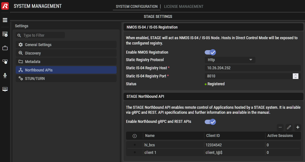
For more information about System Management > System Configuration, see System Management.
Enabling Northbound AMWA MNOS IS-04 and IS-05
When this option is enabled, STAGE will act as an AMWA NMOS IS-04 / IS-05 Node. Hosts that are enabled as Direct Control Mode (see below) will register itself to the NMOS Registry configured here.
|
Enable NMOS Registration |
Set to register this STAGE instance as an AMWA NMOS IS-04 / IS-05 Node. For this, Direct Control Mode (see below) must be enabled. |
|---|---|
|
Static Registry Protocol Http |
Set the communication security level used by the AMWA NMOS registry. Http: Communication is in clear text. Https: Communication with the NMOS Registry is encrypted. |
|
Static IS-04 Registry Host |
Set the AMWA NMOS Registry’s IP address. |
|
Static IS-04 Registry Port |
Set the AMWA NMOS Registry’s port number. |
|
Status |
Shows STAGE’s current connection status with the NMOS Registry. |
Enabling gRPC Northbound API
When this option is enabled, STAGE allows northbound gRPC and REST control communication with a BCS for remote control of Applications hosted by this STAGE instance. See STAGE Northbound API.
Enabling Direct Control Mode
The Direct Control Mode is enabled in System Commissioning, Configuration tab for the selected SAME DSP Engine. See also SAME DSP Engine Configuration for more details about the Setup Tab.
Once enabled, extra configuration tabs become available.
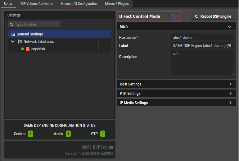
Extra Configuration Tabs with Direct Control Mode
In System Commissioning, the following tabs are available. Once Direct Control Mode is enabled, extra configuration tabs become available that you must also configure to make this operating mode work.
|
System Commissioning, Configuration Tab |
Available in Standard Mode (non-Direct) |
Available in Direct Control Mode |
Description |
|---|---|---|---|
|
Setup |
|
|
Configure the SAME DSP Engine’s network configuration parameters. See SAME DSP Engine Configuration. |
|
DSP Volume Activation |
|
|
This defines the audio processing (mixers and plugins) to make available for use on this SAME DSP-Engine. See SAME DSP-Engine Volume Activation Tab. |
|
Manual I/O Configuration |
|
|
Configure the SAME DSP Engine’s Audio stream inputs and outputs. See #Manual-I/O-Configuration-Tab, below. |
|
Mixers / Plugins |
|
|
Configure the mixers and plugins that the BMS can automate, by for example, creating Snapshots of a setup that can be recalled. See #Mixers-/-Plugins-Tab, below. |
Manual I/O Configuration Tab
In this tab, you configure the:
-
Receiver audio streams that this SAME DSP Engine is to use for signal processing.
-
Sender audio streams the SAME DSP Engine is to make available on the network for other hosts to use.
-
Patch Matrix to set the audio signal cross-points from input to output (Receiver to Sender).
-
Transfer the SAME DSP processing from another SAME DSP Engine to the currently selected SAME DSP Engine.
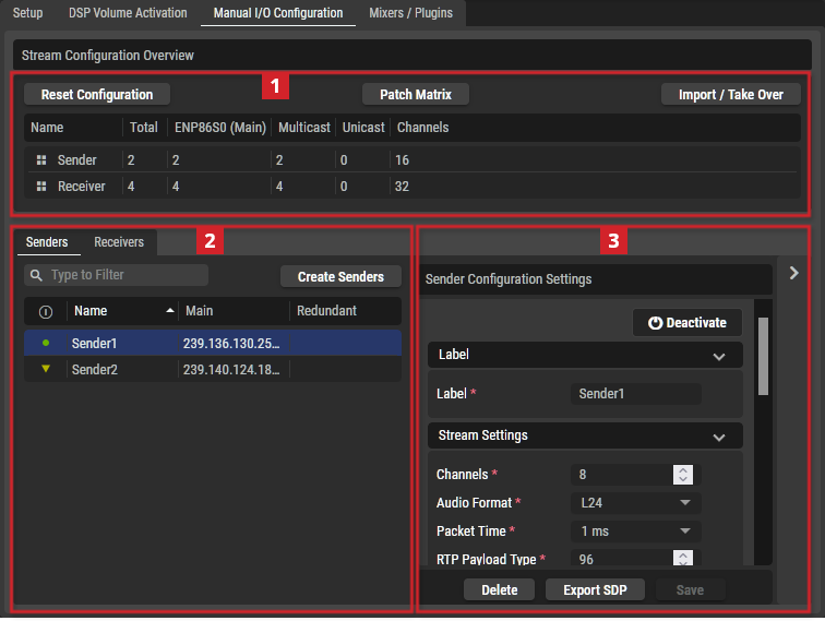
Typical Manual I/O Configuration Tab
|
|
Stream Configuration Overview; shows the number and qualities of the currently configured Senders and Receivers. |
|
|---|---|---|
|
Reset Configuration |
Click to remove all configured Sender and Receiver streams from this SAME DSP Engine. |
|
|
Patch Matrix |
Create Crosspoints to connect the I/Os of the various SAME DSP Engine Sources and Destinations. This is the similar to how you make crosspoints in the Signal Management tab however, there is no Crosspoint Processing available. See STAGE Configuring a Job Setup for more information about how configure crosspoints. For users of the Adobe Acrobat (PDF) version of this user guide, see Configuring a Job Setup in the STAGE User Guide. See SAME Resources. |
|
|
Import / Take Over |
Shift processing from another SAME DSP Engine to the currently selected SAME DSP Engine. See #Import-/-Take-Over-Stream-Configuration. |
|
|
Name |
Shows the signal direction for this row’s parameters: Sender or Receiver. |
|
|
Total |
Shows the total number of senders/receivers configured for this SAME DSP Engine. |
|
|
[Network Interface Name] |
Shows the total number of configured senders/receivers per network interface for this SAME DSP Engine. |
|
|
Multicast |
Shows the total number of configured multicast senders/receivers for this SAME DSP Engine. |
|
|
Unicast |
Shows the total number of configured unicast senders/receivers for this SAME DSP Engine. |
|
|
Channels |
Shows the total number of channels for all configured senders/receivers for this SAME DSP Engine. |
|
|
|
Senders / Receivers View; shows the currently configured sender / receiver streams. |
|
|
Sender Tab |
Shows the currently available Sender streams. |
|
|
Create Sender
|
Click to create a new Sender stream. See #Create-Senders-/-Receivers. |
|
|
Receiver Tab |
Shows the currently available Receiver streams. |
|
|
Create Receiver
|
Click to create a new Receiver stream. See #Create-Senders-/-Receivers. |
|
|
Remove
|
Click to remove (delete) the selected Sender / Receiver. |
|
|
Status |
Shows the current streams status. |
|
|
Name |
Shows the stream’s name. |
|
|
Main |
Shows the stream’s Multicast Destination IP Address. |
|
|
Redundant |
Shows the stream’s redundant Multicast Destination IP Address. This is used when you network supports SMPTE ST 2022-7 Hitless Redundancy. |
|
|
|
Sender / Receiver Configuration Settings; Set the current configuration parameters of the selected Sender or Receiver stream. See #Sender-/-Receiver-Configuration-Settings. |
|
|
Activate / Deactivate |
Click to activate or de-activate this stream. |
|
|
Delete |
Click remove this stream. |
|
|
Export SDP |
Click to download the SDP file for this stream. |
|
|
Save |
Click to apply your configuration changes to this stream. |
|


Import / Take Over Stream Configuration
You can import or take over the SAME stream processing being carried out on another SAME DSP Engine to this SAME DSP Engine. This stops the SAME DSP Engine processing the current streams.
Proceed as follows:
-
Choose how the configuration from another SAME DSP Engine is to be brought into this SAME DSP Engine.
Import: Bring over the SAME DSP Engine’s configuration into the current SAME DSP Engine only. This makes this new configuration available when necessary in the future.
Take Over: Bring over the SAME DSP Engine’s configuration into the current SAME DSP Engine and take over the signal processing from the other server so that the current SAME DSP Engine now processes the audio signals.
-
Select an external SAME DSP Engine to Import / Take Over in Third-Party DSP-Engines.
-
Click Import.
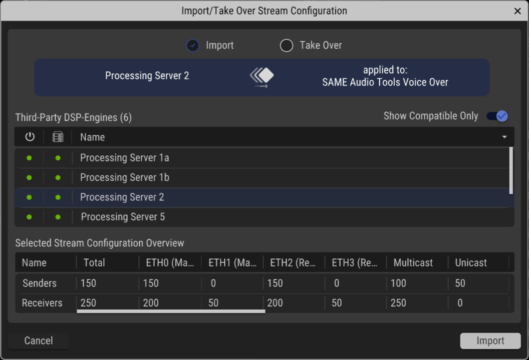
|
Import / Take Over |
Choose how the configuration from another SAME DSP Engine is to be brought into this SAME DSP Engine. Import: Bring over the SAME DSP Engine’s configuration into the current SAME DSP Engine only. This makes this new configuration available when necessary in the future. Take Over: Bring over the SAME DSP Engine’s configuration into the current SAME DSP Engine and take over the signal processing from the other server so that the current SAME DSP Engine now processes the audio signals. |
|
|---|---|---|
|
Third-Party DSP-Engines |
Table shows the SAME DSP Engines available on the network. |
|
|
Show Compatible Only |
Filters the table according to Stream Configuration compatibility. |
|
|
|
The current availability of a host. |
|
|
|
The stream configuration compatibility status of a host. |
|
|
Name |
Shows the Host’s SAME DSP Engine’s name. |
|
|
Selected Stream Configuration Overview |
Shows the currently configured sender / receiver streams for the selected external SAME DSP Engine. |
|
|
Name |
Shows the signal direction for this row’s parameters: Sender or Receiver. |
|
|
Total |
Shows the total number of senders/receivers configured for this SAME DSP Engine. |
|
|
[Network Interface Name] |
Shows the total number of configured senders/receivers per network interface for this SAME DSP Engine. |
|
|
Multicast |
Shows the total number of configured multicast senders/receivers for this SAME DSP Engine. |
|
|
Unicast |
Shows the total number of configured unicast senders/receivers for this SAME DSP Engine. |
|
|
Cancel |
Click to reject your modifications and close the window. |
|
|
Import |
Click to import the stream configuration from the external SAME DSP Engine. |
|


Create Senders / Receivers
In Direct Control Mode, you create Senders and Receivers audio streams. The SAME DSP Engine registers these streams in the AMWA NMOS Registry.
Proceed as follows:
-
Click Create Sender / Create Receiver.
-
Configure the parameters shown below.
-
Click Create.
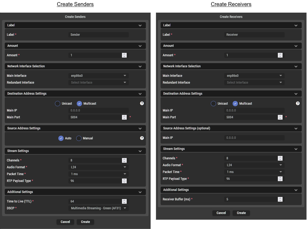
|
Parameter |
Applies to |
Description |
||
|---|---|---|---|---|
|
Sender |
Receiver |
|||
|
Label |
Label |
|
|
Set a friendly name for this host. This host will be identified throughout STAGE and NMOS by this name. |
|
Amount |
Amount |
|
|
Set the number of Senders / Receivers to create. |
|
Network Interface Selection |
Main Interface |
|
|
Set the Ethernet interface that STAGE uses:
|
|
Redundant Interface |
|
|
Set the Ethernet interface that STAGE uses when the host supports SMPTE ST 2022-7 network redundancy, this is the BLUE network on which the host’s secondary media interface is connected. |
|
|
Destination Address Settings |
Unicast / Multicast |
|
|
Set the packet transmission method. Unicast: Use one-to-one connection to stream content. Multicast: Use one-to-many connections to stream content. Senders and receivers support the entire range of multicast IP addresses from |
|
Main IP |
|
|
Set the IP address for this stream. |
|
|
Main Port |
|
|
Set the port number for this stream. |
|
|
Source Address Settings |
Auto / Manual |
|
|
Auto: Set to enable to automatic use the Main IP address as the stream's source IP address. This overrides the Main IP setting. Manual: Use the Main IP setting. |
|
Main IP |
|
|
Set the IP address to use as the stream's source IP address when Auto / Manual is set to Manual. |
|
|
Main IP |
|
|
Set the IP address to use as the stream's source IP address. |
|
|
Stream Settings |
Channels |
|
|
Set the number of supported audio channels. |
|
Audio Format |
|
|
Set the audio sampling bit depth. L16: Linear PCM 16-bit depth. L24: Linear PCM 24-bit depth. L32: Linear PCM 32-bit depth. |
|
|
Packet Time |
|
|
Set the duration of the audio data captured and transmitted in a single digital packet over a network. See https://en.wikipedia.org/wiki/AES67 for more information. Select one of: 125 μs, 250 μs, 333 μs, 500μs, 1 ms, 2 ms, or 4 ms. |
|
|
RTP Payload Type |
|
|
Set the values for dynamically assigned RTP Payload Type (RFC3550) for the audio stream in the range of 96 to 127.
|
|
|
Additional Settings |
Time to Live (TTL) |
|
|
Set the initial TTL value in sent packets. This sets the number of hops through network routers that are allowed before the packet is discarded. When a router receives a multicast packet, it decrements the packet’s TTL value by one. If the packet’s TTL is less than the minimum threshold set on the router’s interface, the packet is discarded. This setting tunes the network to prevent multicast packets from circulating indefinitely, to help contain multicast traffic within specific network segments. |
|
DSCP |
|
|
Set the packet’s quality of service level to allow the network to prioritize packet traffic. See https://en.wikipedia.org/wiki/Differentiated_services. |
|
|
Receiver Buffer (ms) |
|
|
Set the receive buffer size. The buffer size establishes the device’s resistance to network jitter and packet delay. |
|
Sender / Receiver Configuration Settings
The Sender or Receiver settings can be changed. Proceed as follows:
-
Configure the parameters shown below.
-
Click Save.
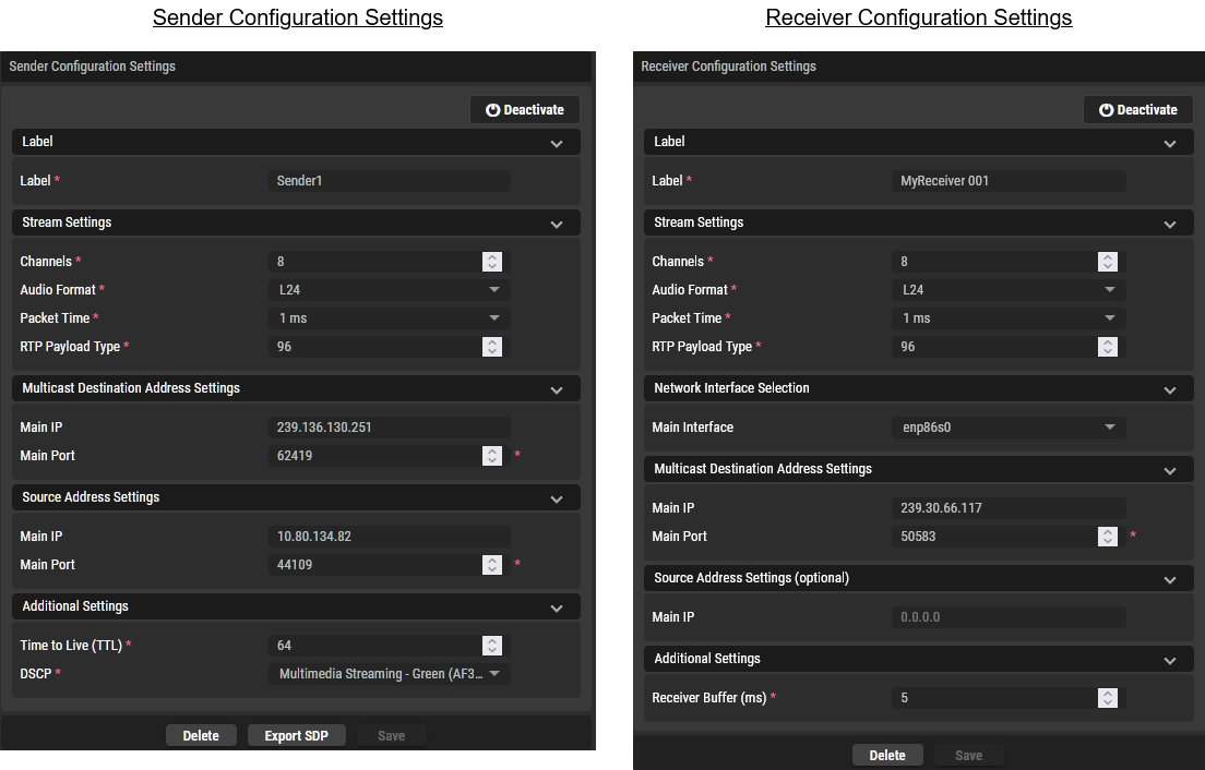
|
Parameter |
Applies to |
Description |
||
|---|---|---|---|---|
|
Sender |
Receiver |
|||
|
Label |
Label |
|
|
Set a friendly name for this host. This host will be identified throughout STAGE and NMOS by this name. |
|
Stream Settings |
Channels |
|
|
Set the number of supported audio channels. |
|
Audio Format |
|
|
Set the audio sampling bit depth. L16: Linear PCM 16-bit depth. L24: Linear PCM 24-bit depth. L32: Linear PCM 32-bit depth. |
|
|
Packet Time |
|
|
Set the duration of the audio data captured and transmitted in a single digital packet over a network. See https://en.wikipedia.org/wiki/AES67 for more information. Select one of: 125 μs, 250 μs, 333 μs, 500μs, 1 ms, 2 ms, or 4 ms. |
|
|
RTP Payload Type |
|
|
Set the values for dynamically assigned RTP Payload Type (RFC3550) for the audio stream in the range of 96 to 127.
|
|
|
Multicast Destination Address Settings |
Main IP |
|
|
Set the IP address for this stream. |
|
Main Port |
|
|
Set the port number for this stream. |
|
|
Source Address Settings |
Main IP |
|
|
Set the IP address to use as the stream's source IP address. |
|
Additional Settings |
Time to Live (TTL) |
|
|
Set the initial TTL value in sent packets. This sets the number of hops through network routers that are allowed before the packet is discarded. When a router receives a multicast packet, it decrements the packet’s TTL value by one. If the packet’s TTL is less than the minimum threshold set on the router’s interface, the packet is discarded. This setting tunes the network to prevent multicast packets from circulating indefinitely, to help contain multicast traffic within specific network segments. |
|
DSCP |
|
|
Set the packet’s quality of service level to allow the network to prioritize packet traffic. |
|
|
Receiver Buffer (ms) |
|
|
Set the receive buffer size. The buffer size establishes the device’s resistance to network jitter and packet delay. |
|
Mixers / Plugins Tab
Configure the mixers and plugins that the BMS can automate, by for example, creating Snapshots of a setup that can be recalled.
Adding Mixers and Plugins for use with Northbound Control
When you add Mixers and Plugins to the SAME DSP Engine in the Volume Activation tab, they become available as a resource to be used under Northbound Control. To add Mixers and Plugins to the SAME DSP Engine, see SAME DSP-Engine Volume Activation Tab.
Add Mixer and Plugin Presets and Snapshots
The configuration of certain SAME Applications can be memorized as a preset for instant recall. Presets can be used by automation to setup a plugin into a known configuration state as required.
-
Click a mixer or plugin listed in the Mixers / Plugins tab. This opens the mixer or plugin.
-
Configure the mixer or plugin as needed.
-
Create a preset / snapshot. To create a preset, see SAME Application Preset Configuration.
-
The preset / snapshot can be invoked through the STAGE Northbound API.
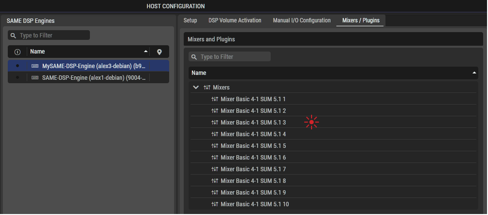
For more information about Presets and Snapshots, see STAGE Northbound API #Presets, #Snapshots, and #Using-Snapshots-and-Presets.
Opening a Mixer’s / Plugin’s Web Interface
Through the STAGE Northbound API, the URLs for plugins and mixer Web interfaces are available, allowing you to integrate these screens into your Broadcast Control System (BCS). See STAGE Northbound API for more information.