Once you have selected a SAME DSP Engine Host Type and a specific SAME DSP Engine Host, you can set its configuration parameters in the configuration tabs shown below.
Overview
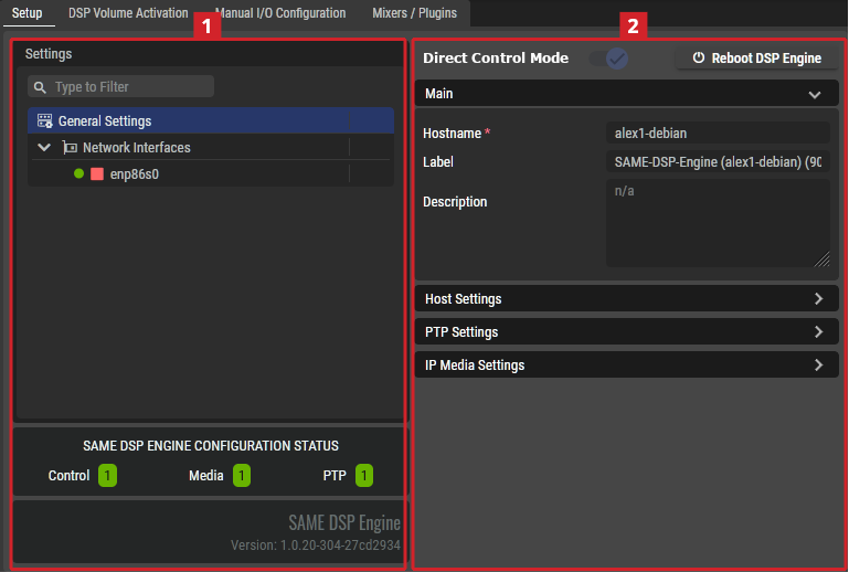
The following configuration tabs are available:
-
Setup. See below.
-
DSP Volume Activation. See SAME DSP-Engine Volume Activation Tab.
When Direct Connection Mode is enabled, the following configuration tabs are also available:
-
Manual I/O Configuration
-
Mixers / Plugin
For more information about Direct Connection Mode, see Putting SAME Under Northbound Control.
Setup Tab
Settings
Depending on the selected item in the Settings section
General Settings
|
Direct Connection Mode |
- |
Enabled: The SAME DSP Engine has features to make it easier to integrate it into a Broadcast Control system (BCS).
In this mode, the SAME DSP Engine does not supports the use of Jobs and Volumes. It is dedicated to being operated by the BCS. For more information about how to setup Direct Mode, see Putting SAME Under Northbound Control. Disabled: The SAME DSP Engine is under local control where you use Jobs and Volumes to operate the audio mixers and plugins. |
|
Reboot DSP Engine |
- |
Click to reboot the SAME DSP Engine. For example, after the first SAME-Server Debian package installation, a reboot is necessary. You must plan this maintenance procedure to be carried out during off hours as it will cause a service outage. |
|
Main |
Hostname |
Shows the hostname of the server on which the selected SAME DSP-Engine is running on. |
|
Label |
Set a friendly name for this SAME DSP-Engine. This SAME DSP-Engine will be identified throughout STAGE by this name. |
|
|
Description |
Set a meaningful description for this SAME DSP-Engine. |
|
|
Host Settings |
Control Port |
Set the control port this SAME DSP-Engine is to use. For more information about the ports used by STAGE, see chapter SAME Default Ports. |
|
Host Engine Control Port |
Set the control port this SAME DSP-Engine is to use. |
|
|
Host Media Control Port |
Set the Host Media control port this SAME DSP-Engine is to use. |
|
|
Host Metrics Listen Port |
Set the Host Metrics port this SAME DSP-Engine is to use. This port can be used by Prometheus for alerts and operational dashboards for example. |
|
|
PTP Settings |
Profile Type |
Set the PTP profile to use as a preset configuration for the below PTP settings. Custom: Freely set the PTP parameter values. AES67-Media: Use the PTP preset values for AES67 media signal type. ST2059-2: Use the PTP preset values for SMPTE ST 2059-2 signal type. AES-R16: Use the PTP preset values for AES-R16 signal type. IEEE1588 Default: Use the PTP preset values for IEEE1588 signal type. |
|
Clock Domain |
Set the domain to use for this SAME DSP-Engine’s PTP clock. PTP domains allow you to use multiple independent PTP clocking subdomains on a single network. |
|
|
Hybrid Mode |
Select between Multicast and Hybrid depending on the network’s PTP configuration.
|
|
|
Priority 1 |
Definition of the Priority-1 of the PTP source.
|
|
|
Priority 2 |
Definition of the Priority-2 of the PTP source.
|
|
|
Announce Interval |
The base-2 logarithm of seconds of the interval of PTP announce messages.
|
|
|
Announce Timeout |
The timeout for the receipt of the aforementioned messages.
|
|
|
Sync Interval |
The base-2 logarithm of seconds of the interval of PTP sync messages.
|
|
|
Delay Request Interval |
The base-2 logarithm of seconds of the interval of PTP delay request messages.
|
|
|
Transport Type |
Set the transport protocol used for PTP packets. UDPv4: [default] Use the IPv4 network addressing scheme. UDPv6: Use the IPv6 network addressing scheme. |
|
|
Delay Mechanism |
Set the PTP network delay calculation method. E2E: [default] Calculates the total network delay between the PTP Grandmaster and this server (PTP TimeReceiver) for the entire path using DELAY_REQUEST and DELAY_RESPONSE messages exchange. This option is easier to implement as intermediate network devices do not have to be PTP aware, but his is at the expense of accuracy as individual link delays cannot be compensated for. P2P: Calculates the total network delay between the PTP Grandmaster and this server (PTP TimeReceiver) by tallying up the delay of each network device in the pathway using Pdelay_Req and Pdelay_Resp messages between adjacent ports. This requires all intermediate network elements to be PTP-aware. |
|
|
Follower Only |
Set the PTP TimeReceiver / TimeTransmitter mode. Enabled: This SAME DSP-Engine is to be a PTP TimeReceiver only. Disabled: This SAME DSP-Engine is to be a PTP TimeReceiver and PTP TimeTransmitter. |
|
|
Status |
Shows the device’s current PTP synchronization state.
|
|
|
IP Media Settings |
Sampling Rate |
Set this SAME DSP-Engine’s operating audio sampling data rate. 44.1 kHz, 48 kHz, or 96 kHz. |
|
Preferred SyncMode |
Set the PTP SyncMode. Adaptive: [default] Allows some offset from the PTP Grandmaster. Strict: [Preferred] Tolerates less offset from the PTP Grandmaster. |
|
|
System Channels |
Set the maximum number of channels this SAME DSP-Engine is to support. Default: 1024, range: 2 … 1536 |
|
|
Default Receiver Buffer (ms) |
Set the nominal receive buffer size. The buffer size establishes the device’s resistance to network jitter and packet delay. |
|
|
Max. Receiver Buffer |
Set the maximum allowed buffer size. |
|
|
Default Send Packet Time |
Set the quantity of audio samples to pack together inside every IP packet. Having longer packet time (more audio samples stored in each IP packet) will produce less IP packet overhead and thus a more efficient network bandwidth usage, while having a smaller packet time (fewer audio samples stored in each IP packet) results in a better “real-time” exchange of data between the IP sender and the IP receiver. |
|
|
Default RTP Payload Type |
Set the values for dynamically assigned RTP Payload Type (RFC3550) for the signal in the range of 96 to 127. Values between 0 and 95 should not be used as they are either reserved or unassigned. The default values are:
|
|
|
Default TTL |
Set the packet’s Time to Live. This sets the number of times a packet can pass through a switch / router before the packet is discarded. Setting a low value helps to prevent packets from looping in a network indefinitely, unnecessarily using up network bandwidth. |
|
|
Default DSCP |
Set the packet’s quality of service level to allow the network to prioritize packet traffic. |
|
|
Sample Buffer Time |
Set the amount of audio buffer:
[default: 100 ms] |
|
|
AES67 Packet Time |
Packet time is the real-time duration of media data in a packet. Samples per packet are calculated from packet time and sampling rate. Short packet time allows for lower latency but requires more bandwidth due to overhead. Implemented for interoperability reasons. (0.125, 0.250, 0.333, 1.000, 2.000 or 4.000 ms). Default: 1.000 ms. The ptime must be sufficient to allow all the audio samples of a whole frame to be sent. A ptime also corresponds to a "number of samples per IP packet", and an audio sample is 3 bytes at 48 kHz sampling rate. Therefore, sending 16 channels with a ptime of 1 ms is NOT possible as (16 * 3 * 48) = 2304 bytes, as the maximum number of bytes per IP packet is 1440. See https://en.wikipedia.org/wiki/AES67 for more information. |
Network Interfaces
Under Network Interfaces, one or more of the host’s network interfaces are shown. In a sequential manner, select a network interface and configure it, then select the next network interface to configure.
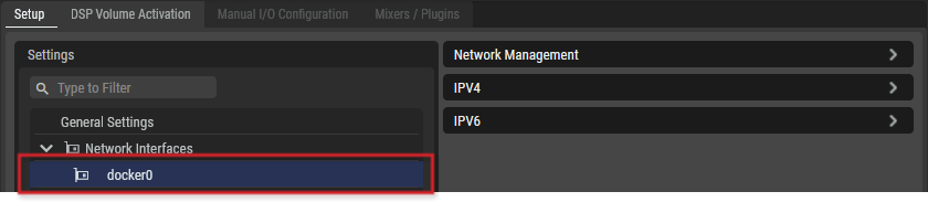
SAME DSP-Engine Network Management
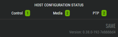
As you are configuring the SAME SAME DSP-Engine-Engine Network Interfaces, the number of Ethernet ports assigned to Control, Media, and PTP signals are tracked in the Host Configuration Status.