This view is used to create and manage virtual SmartPanels that can be used on smartphones, tablets or in a web browser on a computer. Each STAGE member uses a separate virtual SmartPanel in STAGE.
Overview
Failed to load the diagram preview image.
Authentication Required
Page ID: 799998315
Virtual SmartPanel - Function Builder
The PORTS, KEY BUILDER and CONFIGURED KEYS sections can be expanded/collapsed by clicking on the left
Using the Function Builder view
Adding a Virtual SmartPanel
-
In the PORTS section, select a Port to which you want to add a new Virtual SmartPanel key layout.
-
In the KEY LAYOUT EDITOR, click

-
Select the Virtual SmartPanel Type (VSP Browser, VSP Smartphone, or VSP Tablet) and click

Only one of each Virtual SmartPanel type can be added per selected port. -
In case of a VSP Browser was selected, define the matrix arrangement with up to 32 keys per keybank, in any arrangement (1×32, 2×16 … 16×2, 32×1).
-
If the Key Library already has keys in it, for example, from when a key layout has been previously programmed with one or more intercom resources for the selected port, a popup asks whether the keys from the key library should be added to this Virtual SmartPanel.
-
Click

-
Click

-
The new device will appear in the KEY LAYOUT EDITOR section as a new tab.
Programming a Key Function
-
In the PORTS section, select a Port for which a key function is to be programmed.
The content in the KEY BUILDER column provides information on which Intercom Functions, Intercom Resource Types and Intercom Resources are available for the selected Port. -
Optional: To reduce the number of Intercom Resources, you can filter by:
-
selecting one Intercom Function.
-
selecting one Intercom Resource Type.
-
text filtering the Intercom Resources.
-
-
If a Virtual Smartpanel does not yet exist, add it. See section #Adding-a-Virtual-SmartPanel.
-
In the KEY BUILDER section, drag an Intercom Resource (with the corresponding function) and drop it…
-
on a key in the KEY LAYOUT EDITOR.
The related function is programmed on that key. If there is already a function programmed on that key, a dialog is opened to decide to:-
Add the new function on top of the existing function on that key (stacked function).
In this case, all stacked functions will be triggered together when the key is activated. -
Replace the existing function with the new function on this key.
-
-
in the KEY LIBRARY.
The Key Library holds all functions which are configured on all keys as source objects so that they can be reused in other key layouts.Failed to load the diagram preview image.
Authentication Required
Page ID: 799998315
-
-
In the KEY DETAILS, configure the properties of the key.
-
Continue to drag Intercom Resources from the KEY BUILDER and drop them onto the keys in the KEY LAYOUT EDITOR to build up the necessary intercom channels that the Virtual SmartPanel user will have access to. If no Intercom Function is selected, the system always creates a...
-
Talk function for Ports, IFBs, Groups and Outputs.
-
Listen function for Inputs.
-
Talk & Monitor function for Conferences.
-
More than one Intercom Resources can be added to the same key in the KEY LAYOUT EDITOR, as a stacked key function, so that when using the key, it will communicate with all stacked intercom channels at once.
-
Optional: To conveniently add all keys that were previously programmed for the selected port, click on the context menu


Moving an Intercom Resource to another Key
In the KEY LAYOUT EDITOR, change the order of the Keys by Drag and Drop. Click outside of the text region.
Configuring a Key
You can change a key’s properties such as the label, color, and so on.
-
Select a key in the KEY LAYOUT EDITOR or in the KEY LIBRARY.
-
Configure the key’s properties in the KEY DETAILS.
-
Click Update in Key Details. When you update your changes to a key, you can either:
-
Create a new key object that will be applied to the Key Layout Editor and this new key will be added to the Key Library.
-
Update the key object in the Key Library and also update all instances where this key is used on all key layouts.
-
Live-View and Control of a User’s Virtual SmartPanel Instance
Should a Virtual SmartPanel user be experiencing difficulties with using their Virtual SmartPanel instance, or you want to demonstrate its features for training purposes, you can live view and take remote-control of their user interface.
-
Have the user connect to and login to their Virtual SmartPanel instance.
-
In the PORTS section, select the Port that the Virtual SmartPanel user is connected to.
-
In the KEY LAYOUT EDITOR, select the Virtual SmartPanel tab that corresponds with the Virtual SmartPanel that the user is currently using. The status of a currently active Virtual SmartPanel is
-
Click Live View & Remote Control.
A Virtual SmartPanel Browser opens where you can see and use the user’s Virtual SmartPanel instance.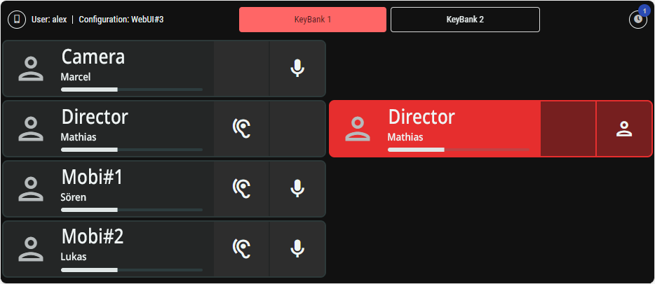
-
Optionally take control of the Virtual SmartPanel user instance by clicking a keybank, an audio level, and so on.
-
Click

Removing a Stacked Key Function from a Key
-
In the PORTS section, select the port that has the key layout with a stacked intercom resource key that is to be removed.
-
In the KEY LAYOUT EDITOR, select the Virtual SmartPanel that has the stacked intercom resource key to be removed.
-
In the device preview, select the key from which the stacked intercom resource key to be removed.
-
In the KEY DETAILS, click on the

Failed to load the diagram preview image.
Authentication Required
Page ID: 799998315
Removing a Key from a Device (with all programmed functions)
-
In the PORTS section, select the port that has the Virtual SmartPanel with the key that is to be removed.
-
In the KEY LAYOUT EDITOR, select the Virtual SmartPanel that has the key to be removed.
-
In the device preview, click on the key that is to be removed.
-
Press Delete on your keyboard.
-
Drag the key from the KEY LAYOUT EDITOR and drop it directly next to the virtual SmartPanel when the mouse pointer has changed to the Discard

Failed to load the diagram preview image.
Authentication Required
Page ID: 799998315
-
Removing all Keys from all Devices (with all programmed functions)
This action clears all Keys on all Virtual Devices including their programmed functions.
This action can not be undone. Be sure that this is intentional.
The Virtual Devices themselves are not deleted.
-
In the PORTS section, select the port that has the Virtual SmartPanel with the keys that are to be removed.
-
In the KEY LIBRARY, click on the context menu

-
Click to confirm this action.
Failed to load the diagram preview image.
Authentication Required
Page ID: 799998315
Copy - Paste Key Layouts
Once you have created and applied a Key Layout for a port, you can copy the Key Layout to another port to speed system setup.
-
In the PORTS section, right-click a port from which you want to copy its Key Layout and select Copy Port [port name] Key Layouts.
-
In the PORTS section, right-click another port to which you want to apply the Key Layout and select Paste Port [port name] Key Layouts.
Failed to load the diagram preview image.
Authentication Required
Page ID: 799998315

PORTS
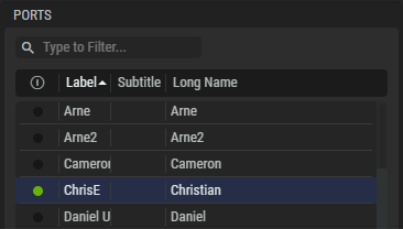
The table lists all intercom resources (ports) that are available in STAGE.
Prerequisite: These are the imported Director ports that come from connected Artist-1024 devices.
-
These resources must first be created with the Director software.
(More information about the configuration in Director can be found in the Director manual.) -
The Artist-1024 must be a device registered in STAGE. See chapter Device Registration #Discovered-Hosts.
Refer to the Director User Guide on how to create STAGE Ports.
|
|
Shows the port’s current connection status. |
|---|---|
|
Label |
Shows the short label text (up to 8 characters) for the port configured in Director. |
|
Subtitle |
Shows the subtitle label text (up to 16 characters) for the port configured in Director. |
|
Long name |
Shows the long name text (up to 16 characters) for the port configured in Director. |
Without an Artist-1024 connection, the following ports are displayed as an example: Audio, Camera 1/2, Editor, Field Engineer, Field Producer, and PA.

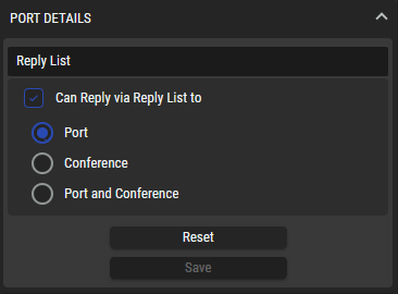
Port Details
This section can be expanded/collapsed by clicking on the up ![]()
![]()
You can set whether the selected Member has the option to reply to a Member and/or Conference.
|
Can Reply via Reply List to |
Set whether the selected Member has the option to reply to a Member and/or Conference. Port: A point-to-point call from a caller (source) to a target (destination). It is the standard function for communication between two individuals. Conference: A multipoint-to-multipoint function between the multiple members of a conference. Every member can talk into the conference at the same time and hear the sum of all active members (if they have the necessary privileges). Port and Conference: Both reply methods are supported. |
|---|---|
|
Reset |
Click to delete all Key Layouts and clear the Key Library for this Port. |
|
Save |
Click to save your changes. |

Intercom Functions
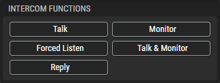
Select one of the following Intercom Functions to pre-filter the available content in the sections Intercom Resource Types and Intercom Resources.
|
Talk |
Toggles a filter to show/hide intercom resources that can be the destination of a Talk function. The Talk function is a call from the interface that activates the command (source) to a target (destination). The destination can be a single Port, a Group, an IFB or a general Output such as a 4-wire or MADI channel. |
|---|---|
|
Monitor |
Toggles a filter to show/hide intercom resources that can be an input of a Monitor function. The Monitor function listens to the outgoing audio signals of a Port, an IFB, a Conference or a general Input such as a 4-wire or MADI channel. |
|
Forced Listen |
Toggles a filter to show/hide intercom resources that can be the input of a Forced Listen function. The Forced Listen function listens to the audio signal audio signal of a Port or Input. The difference to the Monitor function is that that the microphone on the remote control panel is opened even if it is not actively performing a talk function. |
|
Talk & Monitor |
Toggles a filter to show/hide intercom resources that can be the destination/input of a Talk & Monitor function. This is an combined function of the individual functions Talk and Listen to a Port, an IFB or a Conference. |
|
Reply |
Toggles a filter to show/hide intercom resources that can be the destination of a Reply command. The Reply command offers an easy-to-use call-back function. The last incoming call is automatically displayed in the reply key. |

Intercom Resource Types
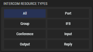
All Intercom Resource Types (hardware / virtual devices) are displayed that correspond to the Intercom Functions selection above. Select one of the following Intercom Resource Types to pre-filter the available content in the section Intercom Resources.
|
All |
Click to clear all filters and show all resource types. |
|---|---|
|
Port |
Click to filter on Port resource type. A Port is an endpoint in the intercom system. It can be a caller (source) and/or a target (destination).
|
|
Group |
Click to filter on Group resource types. A group is a collection of multiple ports. A call to a Group is a point-to-multipoint connection. A single port calls several ports at the same time. This method of communication always goes in only one direction. Any answers to the call from group members are always point-to-point calls back to the source. |
|
IFB |
Click to filter on IFB resource types. An IFB is usually used for the exchange of audio in an intercom system with a talent (news speaker, moderator, etc.). |
|
Conference |
Click to filter on Conference resource types. An conference is a collection of multiple ports. A call to a conference is a multipoint-to-multipoint connection. Every member can talk into the conference at the same time and hear the sum of all active members. |
|
Input |
Click to filter on Input resource types. An Input is a caller (source) in the intercom system. |
|
Output |
Click to filter on Output resource types. An Output is a target (destination) in the intercom system. |
|
Reply |
Click to filter on Reply resource types. A Reply is an easy-to-use call-back function. The last incoming call is automatically displayed in the reply key. |

Intercom Resources
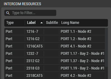
This table lists all the Director Intercom Resources that are available for the Port selected in Ports that correspond to the filtering applied by Intercom Functions and Intercom Resource Types selected above.
Drag an intercom resource onto a key in the Key Layout Editor to link that resource to the key. See section #Programming-a-Key-Function.
-
The key is added to the Key Library.
-
With the key selected, you can configure the key’s properties in Key Details. See section #KEY-DETAILS. Changes to the key’s properties are made to both the key in the Key Layout Editor and to the equivalent key instance in the Key Library.
|
Type |
Shows the Intercom Resource Type (see above). |
|---|---|
|
Label |
Label of the port (8-char) configured in Director. |
|
Subtitle |
Subtitle of the port (16-char) configured in Director. |
|
Long name |
Long name of the port (16-char) configured in Director. |

Key Layout Editor
In this section, the key layout of the Virtual SmartPanel is created individually for the selected Port.
It is possible to add one device type to the selected port.
The following types are available:
-
VSP Smartphone (with a fixed key matrix of 1×8 keys per keybank).
-
VSP Tablet (with a fixed key matrix of 3×8 keys per Keybank).
-
VSP Browser (with a customizable matrix of up to 32 keys per keybank). See section #VSP-Browser.
Failed to load the diagram preview image.
Authentication Required
Page ID: 799998315
Key Layout Editor – Smartphone
|
|
Shows the Virtual SmartPanel’s current status. If it is green, the Virtual SmartPanel is being used by a user.
A Virtual SmartPanel can only be used by one user at a time. |
|---|---|
|
Live View & Remote Control |
Click to live view the screen and control a user’s session when they are connected to a Virtual SmartPanel. This can be used for support and troubleshooting activities. |
|
|
Click to edit the keybank’s name and color. |
|
|
Simulated controls for the VSP Browser.
|
|
|
Click to delete a resource. |
VSP Browser
The VSP Browser offers more flexible layout options as it can be programmed with a customisable matrix of up to 32 keys per keybank in the following arrangements: 1×32, 2×16, 3×10, 4×8, 5×6 and vice versa.
Failed to load the diagram preview image.
Authentication Required
Page ID: 799998315
Key Layout Editor – Browser
The size of the matrix is selected when creating a new layout for a VSP bowser. However, the layout can also be customised later in the layout editor.
Adding Key Columns
-
Columns are created using the small dots that are displayed horizontally at the top and bottom in the VSP preview.
-
Click on the small dot to the left or right of a key column to create a new column in the corresponding position.
Adding Key Rows
-
Rows are created using the small dots that are displayed vertically on the left and right in the VSP preview.
-
Click on the small dot above or below a key row to create a new row in the corresponding position.
Deleting Key Columns
-
Columns are deleted using the small dots that are displayed horizontally at the top and bottom in the VSP preview.
-
Click on the small dot above/below a key column to delete it.
Deleting Key Rows
-
Rows are deleted using the small dots that are displayed vertically on the left and right in the VSP preview.
-
Click on the small dot to the left or right of a key row to delete it.

Key Details
Set the selected key’s properties in Key Details.
Failed to load the diagram preview image.
Authentication Required
Page ID: 799998315
Key Details
This section can be expanded/collapsed by clicking on the up ![]()
![]()
Key Appearance
In the left section of the Key Details, the appearance of the key can be customized.
Failed to load the diagram preview image.
Authentication Required
Page ID: 799998315
When changing the following configuration parameters, the changes are shown in the key preview.
|
Label |
Optionally set the key’s short label text (up to 8 characters) to override the default short label that comes from the resource configured in director. |
|---|---|
|
Subtitle |
Optionally set the key’s subtitle text (up to 16 characters) to override the default subtitle that comes from the resource configured in director. |
|
Icon |
Set the icon to represent the key’s function. |
|
Color |
Set the color code to use as a highlight for the key. |
|
Reset |
Click to reset to the default icon and color. |
|
Cancel |
Click to clear any changes you have made to the key’s properties. |
|
Save |
Click to apply your changes to the key. When you save your changes to a key, you can either:
|
Virtual SmartPanel Key Icons
Icons are used to identify characteristics.
|
Intercom Functions |
||
|---|---|---|
|
Talk |
|
This intercom resource supports outgoing audio (Talk) function from the Virtual SmartPanel to a Port, Group, IFB, Output. |
|
Monitor |
|
This intercom resource supports the monitoring of the outgoing audio (Talk) of a Port, IFB, Conferece, Input. |
|
Forced Listen |
|
This intercom resource supports the forced listening of a Port or Input. This means that the microphone on the remote control panel is opened even if it is not actively performing a talk function. |
|
Talk & Monitor |
|
This intercom resource supports the combined function of the individual functions Talk and Listen to a Port, IFB, Conference. |
|
Reply |
|
This intercom resource supports an easy-to-use call-back function. The last incoming call is automatically displayed in the reply key. |
|
Default Intercom Resource Types However, any icon from a large number of icons can be used to represent a function. |
||
|
Port |
|
Shows when an intercom resource has been configured for a point-to-point call between two ports. For a Reply key, shows that the call is to a Port. |
|
Group |
|
Shows when an intercom resource has been configured for a point-to-multipoint call. Talk from a port to several others at the same time. Functions only from the source to destination. |
|
IFB |
|
Shows when an intercom resource has been configured for an IFB call. |
|
Conference |
|
Shows when an intercom resource has been configured for a multipoint-to-multipoint call. Speak to a conference, listen to a conference. For a Reply key, shows that the call is to a Conference or a Port and Conference. |
|
Input |
|
Shows when an intercom resource has been configured for a general audio input such as a 4-wire or MADI channel. |
|
Output |
|
Shows when an intercom resource has been configured for a general audio output such as a 4-wire or MADI channel. |
|
Reply |
|
The last incoming call is automatically displayed in the reply key. For a Reply key, shows that the call is to a Port. |
Programmed Functions
In the right section of the Key Details, the programmed key functions can be customized.
Failed to load the diagram preview image.
Authentication Required
Page ID: 799998315
The above example shows a key with the following stacked functions:
-
Monitor key function to port ‘Andre’.
-
Talk key function of port ‘Andre’.
To create a stacked key function, see section #Programming-a-Key-Function.
The following actions are available for the programmed key functions:
-
Change the Trigger Mode independently for the incoming and outgoing audio.
-
Momentary: The functions on the key are only active as long as the key is pressed.
-
Latching: The functions on the key are turned on and off by pressing the key.
-
Auto: If the key is pressed briefly (<350ms), it acts like a latching key. If the key is held pressed for longer (>350ms), it acts like a momentary key.
-
-
Click port to open a drop-down list of the ports that can be selected to use with this key function.
-
Click on the down arrow symbol

|
Normalize |
When this function is activated, the user has the option of setting the volume of the corresponding channel to normal level or switching off the mute function. |
|---|---|
|
Notify |
When this function is activated, the user has the option of sending a beep to the remote panel. |
|
Priority |
Set the system-level priority for this intercom resource. The following priorities are available listed in order from lowest priority to highest priority: Low, Normal, High, Paging, and Emergency. The volume-level of lower-priority intercom signals can be reduced by the presence of a higher-priority intercom signal. This allows a higher-priority intercom signal to talk-over lower-priority intercom signals by ducking (lowering or dimming) the volume levels of any lower-priority signals. The amount of ducking to apply to the different priority levels are defined in the Director configuration. See DIM Crosspoint triggered by Priorities in the Director User Manual. For example, if the High priority is set to cut the audio level by -12 dB, each crosspoint to a destination that has a lower priority (in this case Low or Normal priority) will cut the audio level for these lower priority signals by -12 dB for the duration of the High priority call. |
|
Show on Reply |
This function determines whether or not this port is displayed on the Reply key at other panels when this port is calling. This is enabled by default. |

Key Library
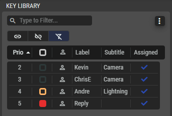
When you configure a key in the Key Layout Editor, the key is automatically added to the Key Library, where it becomes the source object that can be reused on other key layouts. The keys used in the Key Layout Editor point to the key in the Key Library. Modifying a key in the Key Library will change the key wherever it is used in any Key Layout Editor instance. A key can carry several functions (function stack).
It is also possible to create a key directly in the Key Library using drag & drop and to stack functions on this key, even if it is not assigned to a Key Layout Editor.
Drag a key from the Key Library to a key in the Key Layout Editor to create an instance of it.
With the key selected, you can configure the key’s properties in Key Details. Changes to the key’s properties are made to both the key in the Key Library and any equivalent key instances found in the Key Layout Editor.
Click on a heading to sort the keys according to the relevant heading.
|
|
Set a filter to display only content whose search text is found in the name. |
|---|---|
|
|
Click to open a context menu with following options:
|
|
|
Click to show keys that have been assigned to a layout only. See also Assigned below. |
|
|
Click to show keys that have not been assigned to a layout only. |
|
|
Click to clear the filters if they are activated to show all keys. |
|
|
The priority is the order in which the keys have been added, where 1 is the highest priority. This is used to define the priority in which all the buttons have been assigned to a layout (see Add all objects in the context menu above). If the number of configured buttons is greater than is available on the current device, only the buttons with the highest priority are assigned on this layout. |
|
|
Shows the color of the key’s border. |
|
|
Shows the icon used for the key. |
|
|
Shows the key’s label. |
|
|
Shows the key’s subtitle. |
|
|
The |