The StageLink devices offer the following mounting options:
The installation options are shown in the following illustrations using an NSA-003A, but generally apply to all NSA types.
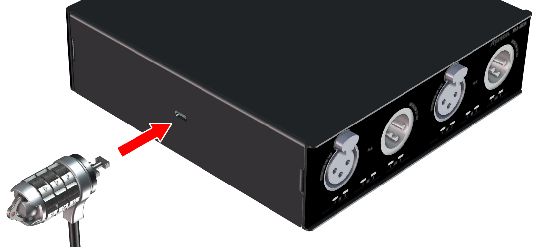
Kensington Opening
There is an opening on the left and right side of the case that is intended for securing the device with a Kensington lock.
VESA Mounting
The NSA is delivered with device feet on the underside. These can be removed in order to use the threaded holes for VESA mounting options (M4, VESA 100x100), which are offered by various manufacturers:
-
Tripod adapter
-
Thread adapter (5/8-inch, 3/8-inch, 1/4-inch)
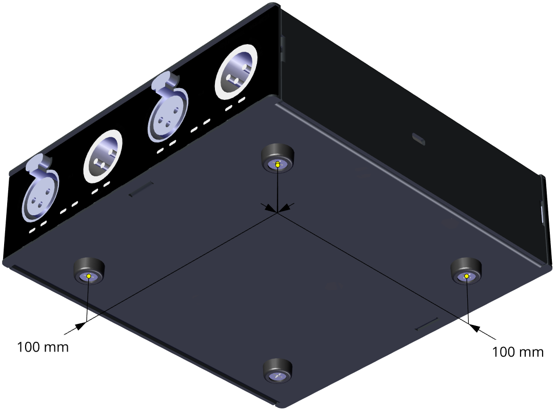
The maximum thread length of the screws inside the housing must not exceed 6 mm, otherwise internal components may be damaged.
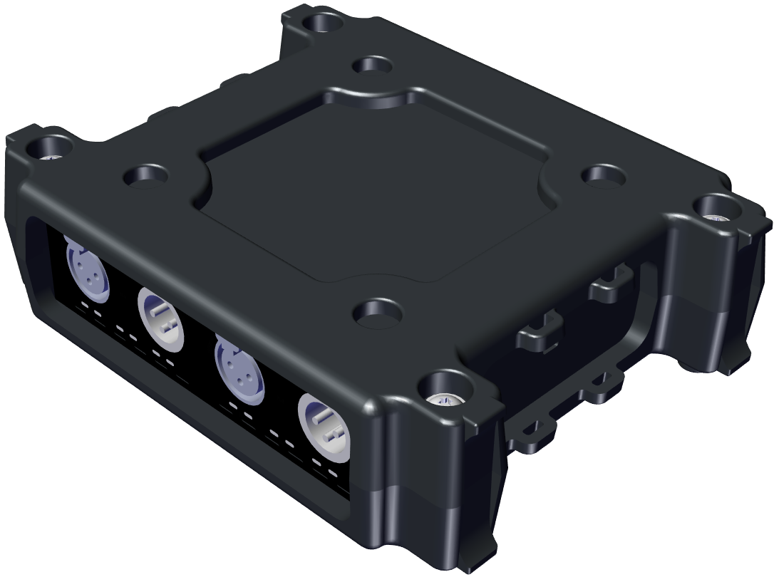
Bumper Case
The rugged bumper case offers the following options:
-
Feet on the bottom
-
Troughs on the top for stacking several devices
-
Feet for vertical positioning
-
Fixing points for cable ties
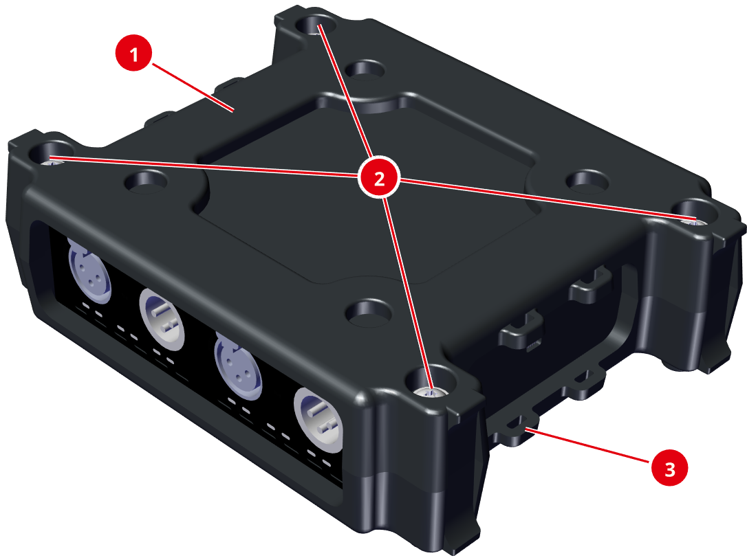
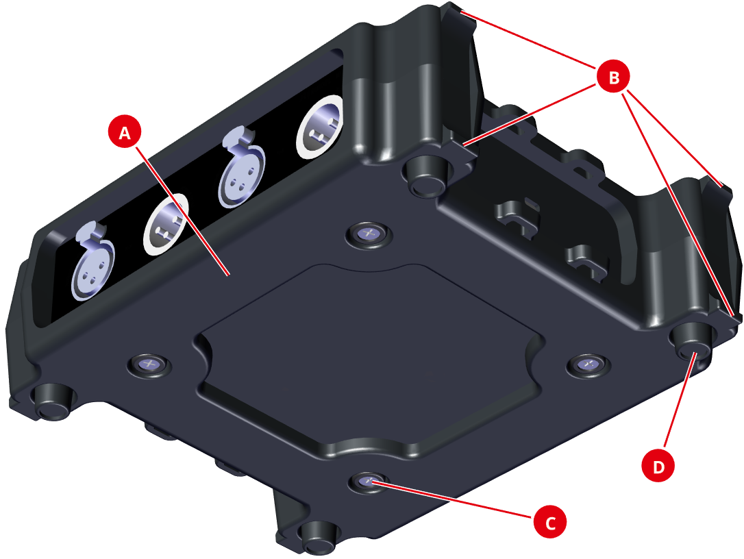
Top
|
|
Upper Shell of the bumper case (identical to the lower shell) |
1x |
|
|
Troughs for stacking multiple devices |
4x |
|
|
Fixing Points for cable ties for device attachment and cable routing
|
8x |
Bottom
|
|
Lower Shell of the bumper case (identical to the upper shell) |
1x |
|
|
Feet for vertical positioning (4x each on the left and right side) |
8x |
|
|
Openings for the device feet of the NSA (4x each in the upper and lower shell) |
8x |
|
|
Bumper Feet for placing or stacking several devices |
4x |
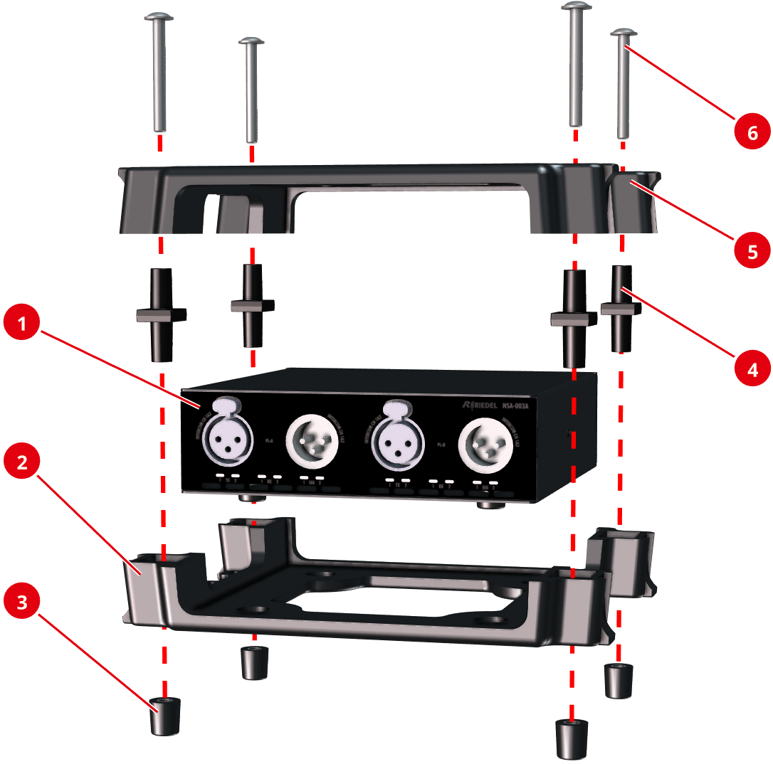
Assembly as a stand-alone device
-
Place the NSA (


-
Place the four spacers (


-
Tighten the shells hand-tight with the four Torx-20 screws (

Using the fixing points
With a total of 8 mounting points, the device can be flexibly attached to wall hooks or poles, for example with cable ties, as shown in the following illustrations.

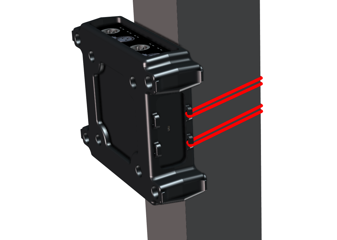
Using the Fixing Points
|
Size of the cable tie feed-through |
max. 3 × 7 mm |
Assembly under the desk
You can mount the device under a desk by replacing the Torx screws with pan head screws. The rubber feet are not required in this case.
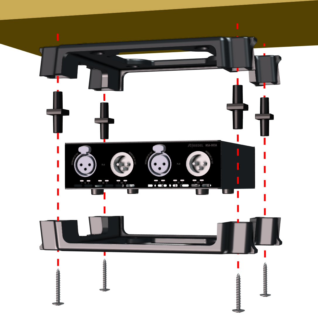
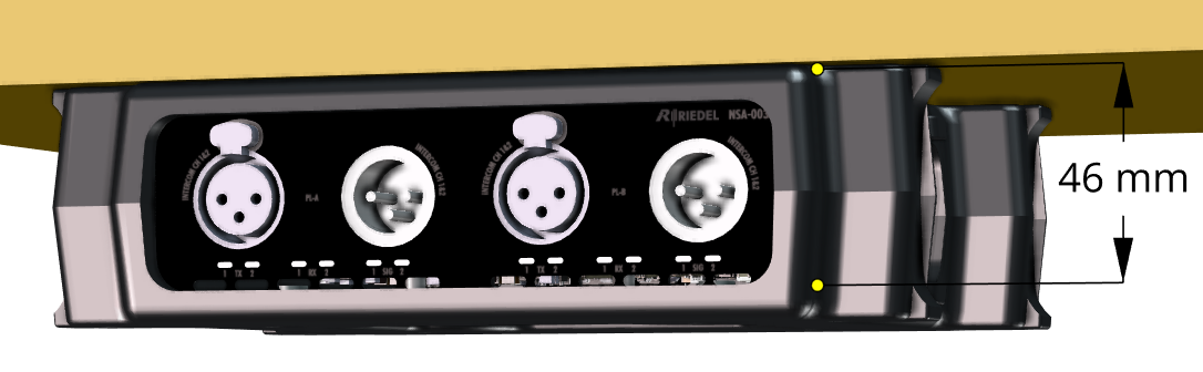
The length of the screw thread in the bumper housing is 46 mm from the lower screw opening to the top of the shell.
assembly under the Desk
|
Screw type |
Pan head screws, no countersunk head screws |
|
Diameter of the screw thread |
max. 5 mm |
|
Diameter of the screw head |
10 ... 12 mm |
|
Screw length |
max. 40 mm, plus thickness of the tabletop |
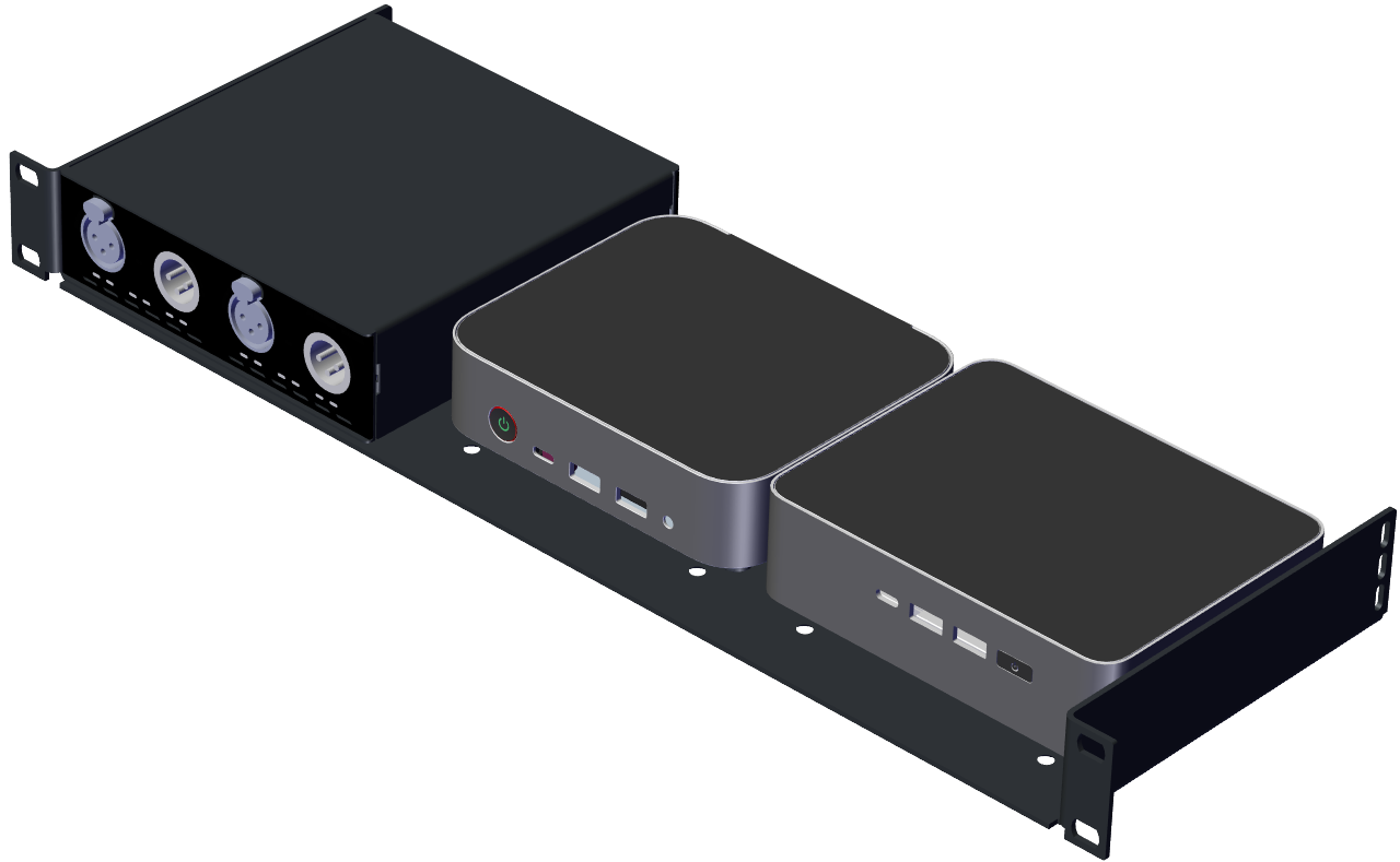
Rack-Shelf NSA 1/3-Rack

The Rack-Shelf offers the option of installing three devices next to each other in a 19” rack.
Each of the three mounting positions offers the following mounting options, not just for StageLink devices:
-
VESA 75
-
VESA 100
-
NUC 14 devices
-
NUC 15 devices
Assembly
Prerequisite
The rubber feet of the StageLink devices must be removed.
-
Turn the device (
-
Place the Rack-Shelf (
-
Screw the supplied screws (
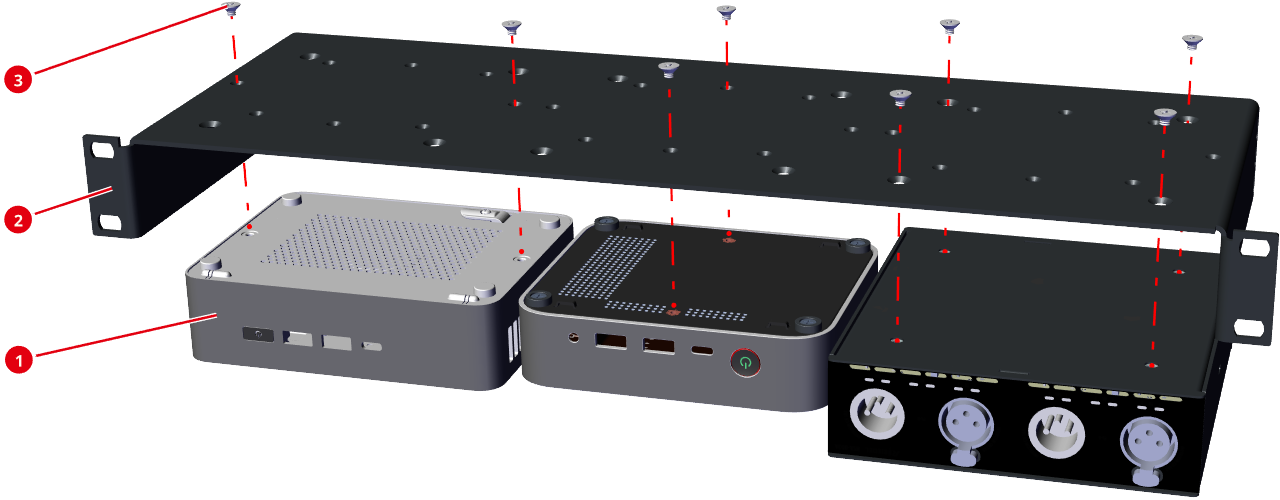
The screws supplied must be used so that the maximum thread length of the screws inside the housing does not exceed 6 mm, otherwise internal components may be damaged.