This is the main configuration page for WebConfig, it is also the “home page” for the WebConfig and you can return to it by pressing the Riedel logo in the title bar.
General Configuration
-
Video Standard:
This is the main video standard used on the entire backend for all record trains. -
Pixel format:
8-bit or 10-bit colour depth pixel formats -
Timecode Input:
Internal or LTC. LTC is required for MultiServer Network -
Video Reference:
Free Run or External. External required for MultiServer Network and/or Super Slomo Cameras. BB or TriLevel supported depending on model. -
Codec:
Default codec available for content export.
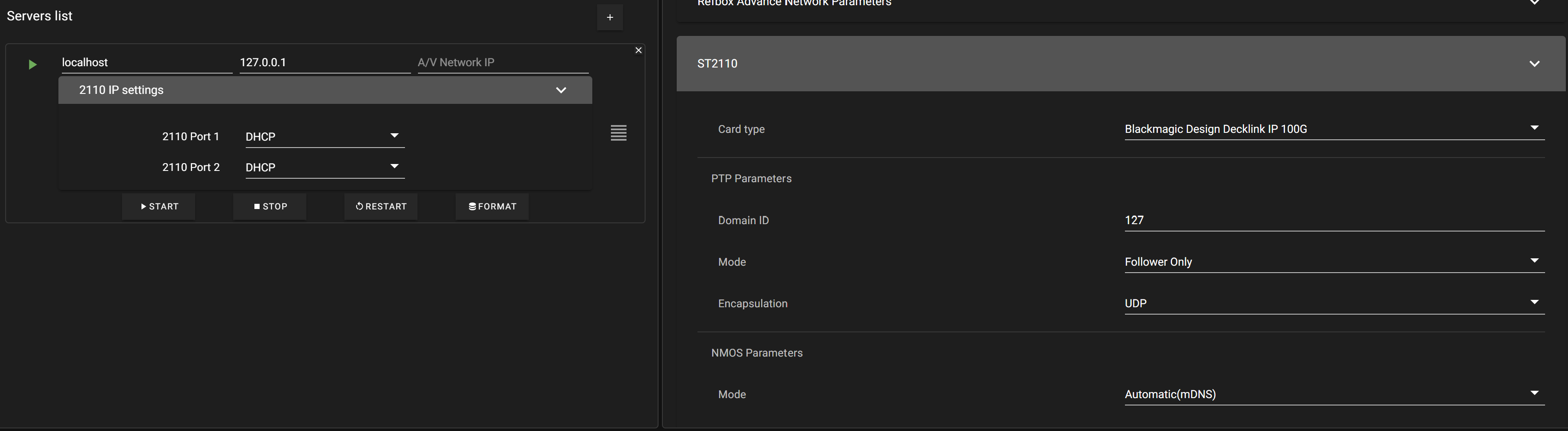
Servers List
This is where you enter your main servers info or the info for networked Servers
-
ALIAS:
The name for the Server indicated. The alias must match the server host name when working in a multi-server network. -
IP/Network Name:
The IP address for the server. -
A/V NETWORK IP:
The IP for the 10GB dedicated network for the Backend Video Network for the indicated server. -
START Button:
Starts the BE on the Indicated Server -
STOP Button:
Stops the BE on the Indicated Server -
Format:
Starts the FORMAT process for the indicated Server. Format deletes ALL content on the server.
Advanced Configuration
Video Configuration
-
Frame Sender Mode:
TCP / UDP
For Video sent to ViBox UI UDP tends to work better in adverse network environments. Must be TCP when using UI Gateway. -
Slow Motion Mode:
Parity Violation / Line Double
Used only for Interlaced Video -
rPGM1 Channel:
Selects program to be assigned to rPGM1 -
rPGM2 Channel:
Selects program to be assigned to rPGM2 -
Aux Activated:
Enable / Disable
Aux outputs controllable in the UI-
Aux1 - PGM1 Clean or Dirty
-
Aux2 - PGM Clean or Dirty
-
-
Send Tally on NDI Inputs:
Enable / Disable
If ViBox is not running in All-in-One mode, it can be useful not to return incorrect Tally information to cameras when running in Review (using RefBox) or Replay (using ViBox SloMo) modes.
Video Network Configuration
-
Multicast IP Address:
Default is 224.0.0.89
Do not change
Do not change without expert guidance, this is used between servers.
-
Multicast Port:
Default is 39100
Do not change
Do not change without expert guidance, this is used between servers.
-
Delay to Live for network Camera:
Default is 18
Option to set frames delay for camera from another server. This is only used in a multi-server network. -
Enhanced local delay:
Enable \ Disable. Enabled forces local camera to be delayed like network cameras.
Pgm Recording
Option to enable record train of the Main Program (PGM 1) outputs in both Clean and Dirty versions.
-
Record PGM 1 Clean:
Enable / Disable-
PGM1 Clean Name: Shortname - 3 letters. | Name: Long name.
-
-
record PGM 1 Dirty:
Enable / Disable-
PGM1 Dirty Name: Shortname - 3 letters. | Name: Long name.
-
Audio Settings
-
Audio Mixer:
Dropdown to select your desired mixer. -
Audio Scrub:
Enable / Disable
Allows for audio while scrubbing -
Audio Slomo:
Enable / Disable
Allows for audio while working with super slow-motion cameras (SloMo) when disabled output is mute at speeds less than 100% -
Send live Audio On Replay Audio Tracks:
Enable / Disable
When disabled audio channels will be mute when player is e2e. -
Audio Advance on Replays:
Set to number of frames -
NDI audio 20DB offset:
Enable / Disable
When enabled NDI audio inputs have a -20db offset.
Sony Protocol
Sony RS242 BBW75- Requires specific hardware.
-
Device ID1:
Set to numerical value
Default is 242 -
Device ID2:
Set to numerical value
Default is 192 -
PGM1 Port:
Disable / COM# -
PGM2 Port:
Disable / COM# -
PGM3 Port:
Disable / COM# -
PGM4 Port:
Disable / COM# -
PGM5 Port:
Disable / COM# -
PGM6 Port:
Disable / COM# -
PGM7 Port:
Disable / COM# -
PGM8 Port:
Disable / COM#
Graphics Settings
-
External Graphics Mode:
Disable / NDI-
1ST NDI Channel Name: Dropdown to select List of available NDI channels detected.
-
2ND NDI Channel Name: Dropdown to select List of available NDI channels detected.
-
-
Layer 1(Front):
Draggable to select keyer priority -
Layer 2:
Draggable to select keyer priority -
Layer 3:
Draggable to select keyer priority -
Layer 4:
Draggable to select keyer priority -
RTD on PGM Clean:
Enable / Disable
Ability to force an RTD on the Clean PGM output.
GPI
-
GPI1:
Option to Select event to trigger on GPI, Second option to further control -
GPI2:
Option to Select event to trigger on GPI, Second option to further control -
GPI3:
Option to Select event to trigger on GPI, Second option to further control -
GPI4:
Option to Select event to trigger on GPI, Second option to further control -
GPI5:
Option to Select event to trigger on GPI, Second option to further control -
GPI6:
Option to Select event to trigger on GPI, Second option to further control -
GPI7:
Option to Select event to trigger on GPI, Second option to further control -
GPI8:
Option to Select event to trigger on GPI, Second option to further control
GPO
-
GPO1:
Option to select GPO On event from UI, Section option to further control event -
GPO2:
Option to select GPO On event from UI, Section option to further control event -
GPO3:
Option to select GPO On event from UI, Section option to further control event -
GPO4:
Option to select GPO On event from UI, Section option to further control event -
GPO5:
Option to select GPO On event from UI, Section option to further control event -
GPO6:
Option to select GPO On event from UI, Section option to further control event -
GPO7:
Option to select GPO On event from UI, Section option to further control event -
GPO8:
Option to select GPO On event from UI, Section option to further control event -
GPO9:
Option to select GPO On event from UI, Section option to further control event -
GPO10:
Option to select GPO On event from UI, Section option to further control event -
GPO11:
Option to select GPO On event from UI, Section option to further control event -
GPO12:
Option to select GPO On event from UI, Section option to further control event -
GPO13:
Option to select GPO On event from UI, Section option to further control event -
GPO14:
Option to select GPO On event from UI, Section option to further control event -
GPO15:
Option to select GPO On event from UI, Section option to further control event -
GPO16:
Option to select GPO On event from UI, Section option to further control event
TSL - General
-
TSL input:
ON / OFF -
Left Output:
ON / OFF -
Left Output Color:
No color/Red/Green/Amber -
Right output:
ON / OFF -
Right Output Color:
NO COLOR/Red/Green/Amber
TSL for Input Channels (UMD & Tally for Cameras)
-
External Graphics 1:
Enable / Disable
Option SCREEN, Option DISPLAY -
External Graphics 2:
Enable / Disable
Option SCREEN, Option DISPLAY -
CAM01:
Enable / Disable
Option SCREEN, Option DISPLAY -
CAM02:
Enable / Disable
Option SCREEN, Option DISPLAY -
CAM03:
Enable / Disable
Option SCREEN, Option DISPLAY -
CAM04:
Enable / Disable
Option SCREEN, Option DISPLAY -
CAM05:
Enable / Disable
Option SCREEN, Option DISPLAY -
CAM06:
Enable / Disable
Option SCREEN, Option DISPLAY
TSL for PGM Channels (Tally for PGMs)
-
PGM 1:
Enable / Disable
Option SCREEN, Option DISPLAY -
PGM 2:
Enable / Disable
Option SCREEN, Option DISPLAY
Refbox Advanced Network Parameters
-
Broadcast DNX IP:
Set to IP
Only used in specific applications -
Network Mode:
Enable / Disable
Only used in specific applications
ST2110
-
Card Type:
Disabled / Blackmagic Design Decklink IP 100G -
PTP Parameters:
Settings for your PTP domain and ST 2110 card behaviour.-
Domain ID:
Set to numerical value
Default is 127 -
Mode:
Follower Only / Follower/Leader -
Encapsulation:
UDP / Ethernet
-
-
NMOS Parameters
-
Mode:
Automatic(mDNS) / Manual Registry
-
Blackmagic Decklink IP 100G QSFP Port Address
When the Blackmagic Decklink IP 100G card is selected, the cards 100G QSFP port IP addresses will be displayed in the Servers List, with the ports displayed underneath the Server settings.
Under NMOS control these IP addresses can change and will update automatically.
For further information on setting up a SimplyLive system in ST 2110 please see the ST 2110 Configuration Guide