This chapter lists specific ports/pinouts for the NSA-010C.
On the NSA-010C, the Phoenix connectors on the front replace the D-Sub connectors on the rear, as found on other NSA types.
GPI port
The GPI connector provides 16 individual isolated general purpose inputs and a current-limited auxiliary output voltage on a rugged Phoenix connector.
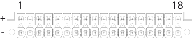
DMCV 1.5/18-G1F-3.5-LR P20THR
DFMC 1.5/18-STF-3.5
|
Pin |
Signal |
Pin |
Signal |
|
1 + / - |
GPIO +5 VDC / GND |
10 + / - |
GP-IN9-P(+) / N(-) |
|
2 + / - |
GP-IN1-P(+) / N(-) |
11 + / - |
GP-IN10-P(+) / N(-) |
|
3 + / - |
GP-IN2-P(+) / N(-) |
12 + / - |
GP-IN11-P(+) / N(-) |
|
4 + / - |
GP-IN3-P(+) / N(-) |
13 + / - |
GP-IN12-P(+) / N(-) |
|
5 + / - |
GP-IN4-P(+) / N(-) |
14 + / - |
GP-IN13-P(+) / N(-) |
|
6 + / - |
GP-IN5-P(+) / N(-) |
15 + / - |
GP-IN14-P(+) / N(-) |
|
7 + / - |
GP-IN6-P(+) / N(-) |
16 + / - |
GP-IN15-P(+) / N(-) |
|
8 + / - |
GP-IN7-P(+) / N(-) |
17 + / - |
GP-IN16-P(+) / N(-) |
|
9 + / - |
GP-IN8-P(+) / N(-) |
18 + / - |
GPIO +5 VDC / GND |

-
The input voltage range of the GPI inputs is +5 to +48 VDC (~5 mA constant current limit).
-
The polarity of the inputs is important. The higher potential must be connected to "P(+)".
-
The inputs are galvanically isolated.
-
The switching thresholds are 2.5 VDC max. for the OFF state and 3.5 VDC min. for the ON state.
-
The maximum current of the auxiliary output voltage "GPIO +5V" is limited to 200 mA (constant current limitation).
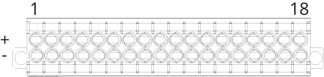
GPO port
The GPO port provides 16 individual isolated general purpose outputs and a current limited auxiliary output voltage on a rugged Phoenix connector.
DMCV 1.5/18-G1F-3.5-LR P20THR
DFMC 1.5/18-STF-3.5
|
Pin |
Signal |
Pin |
Signal |
|
1 + / - |
GPIO +5 VDC / GND |
10 + / - |
GP-OUT9-P(+) / N(-) |
|
2 + / - |
GP-OUT1-P(+) / N(-) |
11 + / - |
GP-OUT10-P(+) / N(-) |
|
3 + / - |
GP-OUT2-P(+) / N(-) |
12 + / - |
GP-OUT11-P(+) / N(-) |
|
4 + / - |
GP-OUT3-P(+) / N(-) |
13 + / - |
GP-OUT12-P(+) / N(-) |
|
5 + / - |
GP-OUT4-P(+) / N(-) |
14 + / - |
GP-OUT13-P(+) / N(-) |
|
6 + / - |
GP-OUT5-P(+) / N(-) |
15 + / - |
GP-OUT14-P(+) / N(-) |
|
7 + / - |
GP-OUT6-P(+) / N(-) |
16 + / - |
GP-OUT15-P(+) / N(-) |
|
8 + / - |
GP-OUT7-P(+) / N(-) |
17 + / - |
GP-OUT16-P(+) / N(-) |
|
9 + / - |
GP-OUT8-P(+) / N(-) |
18 + / - |
GPIO +5 VDC / GND |

-
The maximum GPO output contact rating is 300 mA, 48 VDC (protected by self-resetting fuse).
-
The polarity of the output has no preference.
-
The outputs are galvanically isolated.
-
The maximum current of the auxiliary output voltage "GPIO +5V" is limited to 200 mA (constant current limitation).
Control In port
The Control Voltage Input port provides 2 individual isolated analog inputs and a current limited auxiliary output voltage on a rugged Phoenix connector.
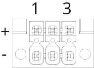
DMCV 1.5/3-G1F-3.5-LR P20THR
DFMC 1.5/3-STF-3.5
|
Pin |
Signal |
|
1 + / - |
GPIO +5 VDC / GND |
|
2 + / - |
CV-IN1-P(+) / N(-) |
|
3 + / - |
CV-IN2-P(+) / N(-) |
-
The analog control voltage input can receive levels up to 5 Vpp max, the switching thresholds can be set in the software.
-
The polarity of the inputs is important. The higher potential must be connected to "P(+)".
-
The inputs are galvanically isolated, but the "N(-)" for all inputs and outputs are connected together to an isolated GND.
-
The maximum current of the auxiliary output voltage "GPIO +5V" is limited to 300 mA (constant current limitation).
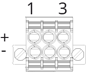
Control Out port
The Control Voltage Output port provides 2 individual isolated analog outputs.
DMCV 1.5/3-G1F-3.5-LR P20THR
DFMC 1.5/3-STF-3.5
|
Pin |
Signal |
|
1 + / - |
Not Connected |
|
2 + / - |
CV-OUT1-P(+) / N(-) |
|
3 + / - |
CV-OUT2-P(+) / N(-) |
-
The analog control voltage output can provide a voltage of up to 5 Vpp max, which can be configured in the software.
-
The polarity of the outputs is important. The higher potential must be connected to "P(+)".
-
The outputs are galvanically isolated, but the "N(-)" for all inputs and outputs are connected together to an isolated GND.
DC IN
The DC-IN input allows the device to be supplied with a voltage of 12 to 57 VDC.

|
Pin |
Signal |
|
1 |
GND |
|
2 |
Not connected |
|
3 |
Not connected |
|
4 |
12 ... 57 VDC |
USB Type-C port
The USB-C port (USB 2.0) functions as device mode. The NSA-010C does not support USB audio.

The USB 2.0 port can supply connected devices with a limited current of max. 500 mA.