This tab is not available on the NSA-004A and NSA-005A.
On this tab, the functions of the GPI inputs and GPO outputs can be defined and tested. Depending on the NSA type, a different number of inputs/outputs are available.
|
|
NSA-003A |
NSA-006A |
NSA-007A |
NSA-008A |
NSA-010C |
|
GPInputs / GPOutputs |
3 / 3 |
3 / 3 |
3 / 3 |
6 / 6 |
16 / 16 |
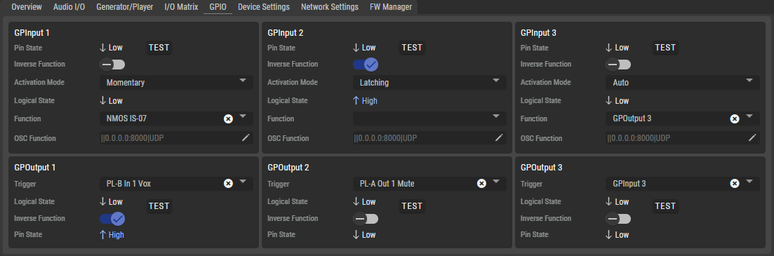
The View selection at the bottom right of the web interface can be used to set whether GPIs and GPOs (All), only GPIs (GPInputs) or only GPOs (GPOutputs) are displayed.
GPInput 1...x
|
Pin State |
Displays the physical state of the input pin: Low (0/off) or High (1/on). |
|
|
TEST |
The state is inverted as a test as long as the button is pressed. This is useful when the external GPI wiring has not yet been installed, but the OSC and NMOS-IS-07 functions need to be tested. |
|
|
Inverse Function |
If activated, the configured function of the input is triggered inverted. |
|
|
Activation Mode |
Defines whether switching is latching, non-latching (momentary) or automatic (short signal: latching, long signal: momentary). |
|
|
Logical State |
Displays the logical state of the input that triggers the configured function. |
|
|
Function |
The selected function will be activated if the logical state is High (1/on). |
|
|
NMOS IS-07 |
Sends a NMOS IS-07 for the high/low state. |
|
|
|
Sends specified parameters to an Open Sound Controller for the high/low state. |
|
|
GPOutput 1 ... x |
Switches the output state depending on the selected input state. |
|
|
<Channel> Mute |
The GPI mutes the <channel>. Available channels for switching:
|
|
|
<Channel> Call*3A |
The GPI initiates a Call at the input of the <channel>. Available channels for switching:
|
|
|
<Channel> MicKill*3A |
The GPI mutes the microphone of the <channel>. Available channels for switching:
|
|
|
OSC Function |
Specifies the OSC parameters to be transmitted to other OSC-compatible devices for the high/low state, as well as the destination device’s IP Address, Port, and Transport Mode.
|
|
|
*3A only for NSA-003A *6-8A only for NSA-006A, NSA-007A, NSA-008A |
||

GPOutput 1...3
|
Trigger |
Selection of the function that is to switch the state of the output pin. |
|
|
NMOS IS-07 |
Receives a NMOS IS-07 for the high/low state. |
|
|
|
Switches the output state depending on the received Open Sound Controller parameter for the high/low state. See chapter Open Sound Control for further information. |
|
|
GPInput 1 ... x |
Switches the output state depending on the selected input state. |
|
|
<Channel> Mute |
The GPO is switched by the Mute function of the <channel>. Available channels for switching:
|
|
|
<Channel> Vox |
The GPO is switched by the Vox function of the <channel>. Available channels for switching:
|
|
|
<Channel> Call*3A |
The GPO is switched by the Call function of the <channel>. Available channels for switching:
|
|
|
<Channel> MicKill*3A |
The GPO is switched by the MicKill function of the <channel>. Available channels for switching:
|
|
|
Logical State |
Shows the logical state of the configured function at the output. |
|
|
Inverse Function |
If activated, the configured function of the output is triggered inverted. |
|
|
Pin State |
Displays the physical state of the output pin: Low (0/off) or High (1/on). |
|
|
TEST |
The state is inverted as a test as long as the button is pressed. This is useful when the external GPO wiring has not yet been installed, but the OSC and NMOS-IS-07 functions need to be tested. |
|
|
*3A only for NSA-003A *6-8A only for NSA-006A, NSA-007A, NSA-008A |
||