
This page describes the hiPush54 (Mark 2) Hardware Panel and its specifications.
hiPush54 (Mark 2)
Mark 2
19-inch 2RU Hardware Panel with 54 buttons and two rotary encoders for operation of the hi system. Each button has a 60 x 32 pixel OLED display to indicate the assigned function. Each encoder has a 15-segment LED meter ring.
Information
Discontinued: This product has been discontinued and is no longer actively maintained or supported. Devices may continue to operate as expected, but future development of this platform is not planned.
Dimensional Views
Front View
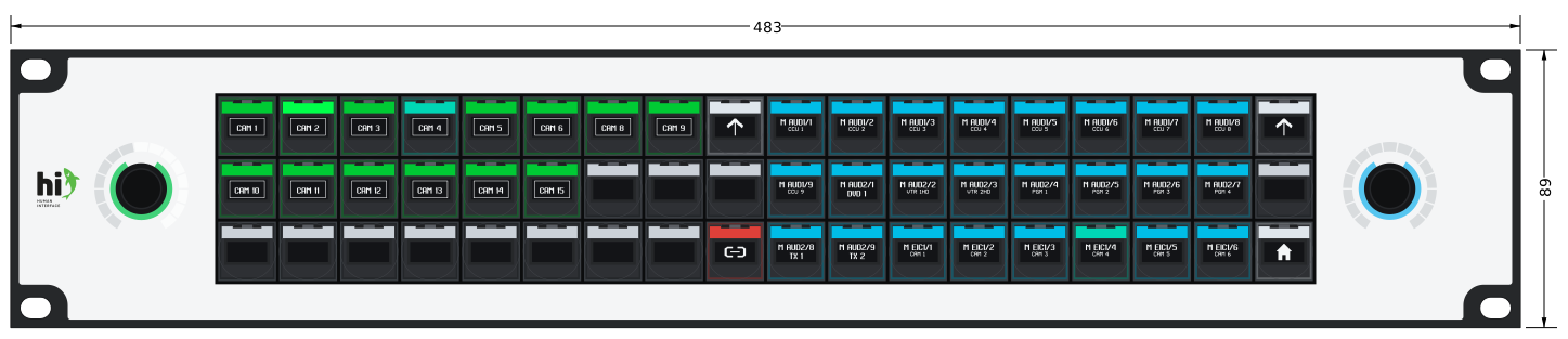
hiPush54 Mark 2 Front View.
Rear View
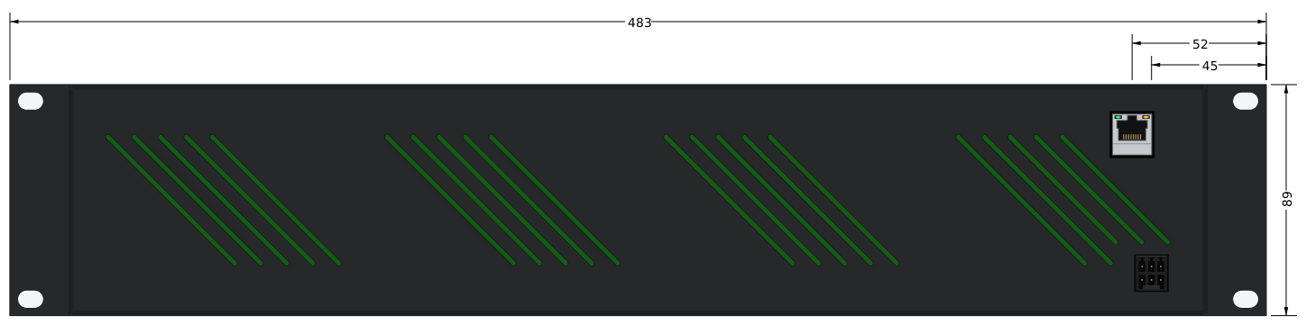
hiPush54 Mark 2 Rear View.
Top View

hiPush54 Mark 2 Top View.
Specifications
|
Regulatory Model |
HI-PNL004 |
|---|---|
|
Number of Switches |
54 |
|
Number of Encoders |
2 |
|
Encoder Meter Indicator |
15-segment LED ring around each encoder |
|
Button Display |
60 x 32 pixel OLED per button |
|
Control Illumination |
RGB backlighting for buttons and encoders |
|
Housing Type |
2 Rack Units |
|
Dimensions |
482.6 x 88.9 x 39 mm (W x H x D) |
|
Network Connection |
RJ45, 100Base-T Ethernet |
|
Storage Temperature Range |
-20 °C to +80 °C |
|
Switch Operating Force |
125 ± 35 gf |
|
Input Voltage |
12 V DC nominal (11 V to 13 V operating range) |
|
Power Consumption |
Max. 20 W |
|
External PSU |
CUI SDI30-12-U-P5 (separate part) |
|
Power Connector Type |
WAGO 713 Series 6-pin |
|
Protection Class |
IP20 |
|
Conformity Marking |
CE |
|
Electromagnetic Compatibility (EMC) |
EN 61000-3-2:2014
|
|
RoHS Reference |
EN 50581:2012 |
|
EC Declaration of Conformity |
Dated 23 August 2019
|
|
Directives Named in Declaration |
EMC Directive 2014/30/EU
|
|
EMC Test Report |
TÜV Rheinland report 28251340 001 for HI-PNL004
|
|
Lifecycle Status |
Discontinued |
Commissioning
For installation and commissioning steps, see Hardware Installation and Commissioning. For the default IP address, web interface port, and network setup, see Hardware Network Configuration. For routine care, see Hardware Cleaning and Maintenance.
Ordering Information
This model is discontinued and is no longer available for new orders. Use the regulatory model in Specifications to identify installed hardware.
Power Connector Pinout
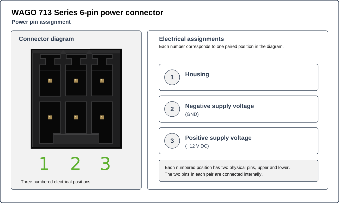
For pin assignments, see Power Connector Pinout.