This tab is not available on the NSA-010C.
This tab is used to define which audio sources (Inputs and AES67 Receivers) are routed to which audio targets (Outputs and AES67 Senders).
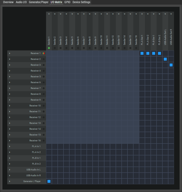
Audio Sources
The left-hand column shows all available audio sources of the NSA from top to bottom.
|
Receiver 1...16 |
AES67 stream inputs with up to 64 channels. Up to 16 channels can be assigned to the destinations per device. The colored dot next to it shows the current status of the stream. |
|
|
|
Receiving an audio stream is not activated. |
|
|
|
With redundant configuration: The audio stream is received on both media interfaces.
|
|
|
|
Only with redundant configuration: An audio stream is received on only one Ethernet connection. |
|
|
|
Reception is activated, but no audio stream is received. |
|
|
|
An audio stream is received, but no audio output is patched. |
|
|
PL-A/B In 1...2*3A |
Inputs of the Partylines A or B with 2 mono channels each. |
|
|
Analog / Digital In*4-6-7A |
Inputs of the Universal Inputs: Analog In TRNS (transparent), Analog In TRIM (trimmed), Digital In L and Digital In R. |
|
|
USB-Audio In L/R |
USB audio input with left and right channel. |
|
|
Generator/Player |
The audio test signal that is defined on the Generator/Player tab. |
|
|
*3A only for NSA-003A *4-6-7A only for NSA-004A, NSA-006A, NSA-007A |
||
Audio Targets
The top row shows all available audio targets of the NSA from left to right.
|
Sender 1...16 |
AES67 stream outputs with up to 64 channels. Up to 16 channels of sources can be assigned per device. The colored dot below shows the current status of the stream. |
|
|
|
Sending an audio stream is not activated. |
|
|
|
An audio stream is sent. |
|
|
|
An audio stream is sent, but no audio source is patched. |
|
|
PL-A/B Out 1...2*3A |
Outputs to the Partylines A or B with 2 mono channels each. |
|
|
Analog / Digital Out 1...2*5-6-7A |
Outputs of the Universal Outputs 1/2: Analog Out, Digital Out L and Digital Out R. |
|
|
USB-Audio Out L/R |
USB audio outputs with left and right channel. |
|
|
*3A only for NSA-003A *5-6-7A only for NSA-005A, NSA-006A, NSA-007A |
||
Crosspoints
The crosspoints determine which audio sources are to be transmitted to which audio targets.
-
A received audio channel of an AES67 stream can be assigned to any number of audio outputs.
-
Only a single audio input can be assigned to an audio output.
If another audio input is assigned to an audio output, the previously assigned crosspoint is removed.
The symbols of the crosspoints of inputs and outputs have the following meaning.
|
|
No crosspoints can be set at light-colored connections. |
|
|
Crosspoints can be set at dark connection points to connect an audio input to an audio output.
|
|
|
Audio Channel: The input channel is assigned to an output channel, but no audio stream is received. |
|
|
Not all source channels of this stream/group are assigned to target channels. |
|
|
Audio Stream/Group: All source channels of this stream/group are assigned to target channels. |
-
Click on a receiver to the left of the matrix or on a sender above the matrix to open its settings on the right-hand side.
-
Configure the audio mapping by clicking on the crosspoint to assign or delete an audio source to an audio target.
-
Changes to the crosspoints are applied directly.
Setting up a Sender Stream
-
Click on a sender above the matrix to open the Sender, Connection and Stream Settings on the right-hand side.
-
Enter the appropriate settings in these fields.
-
Activate the settings by clicking on the Apply button.
-
Start sending the stream by pressing the Play button in the Sender Settings area.
Setting up a Receiver Stream
-
Click on a receiver on the left-hand side of the matrix to open the Receiver, Connection and Stream Settings on the right-hand side.
-
Enter the appropriate settings in these fields.
-
Activate the settings by clicking on the Apply button.
-
Start receiving the stream by pressing the Play button in the Receiver Settings area.
Stopping a Stream
-
Click on a receiver or sender on the left-hand side or above the matrix to open its settings on the right-hand side.
-
Stop the stream by pressing the Stop button in the Sender or Receiver Settings area.
Stream Settings
Click on a Receiver or Sender to open its settings on the right-hand side.
Receiver
|
Receiver Settings |
Name |
Name of the audio stream. |
|
Play Mode |
Synchronous: Audio packets that have no or an invalid PTP timestamp are discarded. This means that only audio signals that are transmitted in a PTP-synchronous network are received. Syntonous: Audio packets with no or an invalid PTP timestamp are received and processed. This can lead to increased delay and jitter. |
|
|
Buffer (ms) |
Selection of the input buffer (1 ... 150 ms) to compensate for runtime differences. The default value is 3 ms. |
|
|
Import SDP |
Loads the settings from an SDP file. |
|
|
Stop / Play |
Starts or stops the audio stream. |
|
|
Connection Settings |
Two individual Ethernet interfaces are available. For redundant operation, both the primary and the secondary interface must be configured. |
|
|
RTP Multicast IP |
Enter the multicast address of the RTP sender (224.0.0.0 ... 239.255.255.254) |
|
|
RTP Multicast Port |
Enter the multicast port of the RTP sender (0 ... 5004 ... 65535) |
|
|
Sender IP |
Enter the IP address of the sender. |
|
|
RTP Enabled |
Activates automatic negotiation of the stream parameters. To do this, the IP address of the RTP sender must be entered in the upper field. |
|
|
Stream Settings |
Channels |
Number of audio channels (1 ... 64) that are available in the audio stream. |
|
Audio Format |
Select the resolution (L16, L24). |
|
|
Packet Time |
Packet time is the real-time duration of media data in a packet. Samples per packet are calculated from packet time and sampling rate. Short packet time allows for lower latency but requires more bandwidth due to overhead. Implemented for interoperability reasons. Depending on selected amount of audio channels and the bit depth, shorter packet times are available. (0.125, 0.250, 0.333, 1.000 or 1.333 ms) |
|
|
Payload Type |
Selection of the Payload type. (96...127) |
|
|
SSRC |
Selection of the synchronization source. (0...32) |
|
|
Time Stamp Offset |
Selection of the Time Stamp Offset. (0...32) |
|
Sender
|
Sender Settings |
Name |
Name of the audio stream. |
|
Export SDP |
Saves the settings in an SDP file. |
|
|
Stop/Play |
Starts or stops the audio stream. |
|
|
Connection Settings |
Two individual Ethernet interfaces are available. For redundant operation, both the primary and the secondary interface must be configured. |
|
|
RTP Multicast IP |
Enter the multicast address of the RTP sender (224.0.0.0 ... 239.255.255.254) |
|
|
RTP Multicast Port |
Enter the multicast port of the RTP sender (0 ... 5004 ... 65535) |
|
|
RTP Enabled |
Selects the media port via which a stream is sent. |
|
|
Stream Settings |
Channels |
Number of audio channels (1 ... 64) that are available in the audio stream. |
|
Audio Format |
Select the resolution (L16, L24). |
|
|
Packet Time |
Packet time is the real-time duration of media data in a packet. Samples per packet are calculated from packet time and sampling rate. Short packet time allows for lower latency but requires more bandwidth due to overhead. Implemented for interoperability reasons. Depending on selected amount of audio channels and the bit depth, shorter packet times are available. (0.125, 0.250, 0.333, 1.000 or 1.333 ms) |
|
|
Payload Type |
Selection of the Payload type. (96...127) |
|