Overview
Failed to load the diagram preview image.
Authentication Required
Page ID: 1644495183
Setup Tab
Settings
Depending on the selected item in the Settings section
General Settings
|
Main |
Hostname |
Shows the hostname of the server on which the selected SAME DSP-Engine is running on. |
|
Label |
Set a friendly name for this SAME DSP-Engine. This SAME DSP-Engine will be identified throughout STAGE by this name. |
|
|
Description |
Set a meaningful description for this SAME DSP-Engine. |
|
|
Host Settings |
Control Port |
Set the control port this SAME DSP-Engine is to use. For more information about the ports used by STAGE, see chapter Default Ports. |
|
Host Engine Control Port |
Set the control port this SAME DSP-Engine is to use. |
|
|
Host Media Control Port |
Set the Host Media control port this SAME DSP-Engine is to use. |
|
|
Host Promtail Listen Port |
Set the Host Promtail control port this SAME DSP-Engine is to use. A Promtail agent can relay the contents of local STAGE logs to a private Grafana Loki instance or Grafana Cloud using this port number. |
|
|
Host Metrics Listen Port |
Set the Host Metrics port this SAME DSP-Engine is to use. This port can be used by Prometheus for alerts and operational dashboards for example. |
|
|
PTP Settings |
Profile Type |
Set the PTP profile to use as a preset configuration for the below PTP settings. Custom: Freely set the PTP parameter values. AES67-Media: Use the PTP preset values for AES67 media signal type. ST2059-2: Use the PTP preset values for SMPTE ST 2059-2 signal type. AES-R16: Use the PTP preset values for AES-R16 signal type. IEEE1588 Default: Use the PTP preset values for IEEE1588 signal type. |
|
Clock Domain |
Set the domain to use for this SAME DSP-Engine’s PTP clock. PTP domains allow you to use multiple independent PTP clocking subdomains on a single network. |
|
|
Priority 1 |
Definition of the Priority-1 of the PTP source.
|
|
|
Priority 2 |
Definition of the Priority-2 of the PTP source.
|
|
|
Announce Interval |
The base-2 logarithm of seconds of the interval of PTP announce messages.
|
|
|
Announce Timeout |
The timeout for the receipt of the aforementioned messages.
|
|
|
Sync Interval |
The base-2 logarithm of seconds of the interval of PTP sync messages.
|
|
|
Delay Request Interval |
The base-2 logarithm of seconds of the interval of PTP delay request messages.
|
|
|
Transport Type |
Set the transport protocol used for PTP packets. UDPv4: [default] Use the IPv4 network addressing scheme. UDPv6: Use the IPv6 network addressing scheme. |
|
|
Delay Mechanism |
Set the PTP network delay calculation method. E2E: [default] Calculates the total network delay between the PTP Grandmaster and this server (PTP TimeReceiver) for the entire path using DELAY_REQUEST and DELAY_RESPONSE messages exchange. This option is easier to implement as intermediate network devices do not have to be PTP aware, but his is at the expense of accuracy as individual link delays cannot be compensated for. P2P: Calculates the total network delay between the PTP Grandmaster and this server (PTP TimeReceiver) by tallying up the delay of each network device in the pathway using Pdelay_Req and Pdelay_Resp messages between adjacent ports. This requires all intermediate network elements to be PTP-aware. |
|
|
Follower Only |
Set the PTP TimeReceiver / TimeTransmitter mode. Enabled: This SAME DSP-Engine is to be a PTP TimeReceiver only. Disabled: This SAME DSP-Engine is to be a PTP TimeReceiver and PTP TimeTransmitter. |
|
|
PTP Status |
Shows the device’s current PTP synchronization state.
|
|
|
IP Media Settings |
Sampling Rate |
Set this SAME DSP-Engine’s operating audio sampling data rate. 44.1 kHz, 48 kHz, or 96 kHz. |
|
Preferred SyncMode |
Set the PTP SyncMode. Adaptive: [default] Strict: |
|
|
System Channels |
Set the maximum number of channels this SAME DSP-Engine is to support. Default: 1024, range: 2 … 1536 |
|
|
Sample Buffer Time |
Set the amount of audio buffer:
[default: 100 ms] |
|
|
AES67 Packet Time |
Packet time is the real-time duration of media data in a packet. Samples per packet are calculated from packet time and sampling rate. Short packet time allows for lower latency but requires more bandwidth due to overhead. Implemented for interoperability reasons. (0.125, 0.250, 0.333, 1.000, 2.000 or 4.000 ms). Default: 1.000 ms. The ptime must be sufficient to allow all the audio samples of a whole frame to be sent. A ptime also corresponds to a "number of samples per IP packet", and an audio sample is 3 bytes at 48 kHz sampling rate. Therefore, sending 16 channels with a ptime of 1 ms is NOT possible as (16 * 3 * 48) = 2304 bytes, as the maximum number of bytes per IP packet is 1440. See https://en.wikipedia.org/wiki/AES67 for more information. |
Network Interfaces
Under Network Interfaces, one or more of the host’s network interfaces are shown. In a sequential manner, select a network interface and configure it, then select the next network interface to configure.
Failed to load the diagram preview image.
Authentication Required
Page ID: 1644495183
SAME DSP-Engine Network Management
See chapter WebRTC Gateway Configuration#Network-Interfaces.
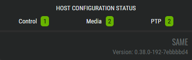
As you are configuring the SAME SAME DSP-Engine-Engine Network Interfaces, the number of Ethernet ports assigned to Control, Media, and PTP signals are tracked in the Host Configuration Status.
SAME DSP-Engine Volume Activation Tab
This defines the audio processing to make available for use on this SAME DSP-Engine. For example, this can be mixers, limiters, and other audio processing plugins.
Failed to load the diagram preview image.
Authentication Required
Page ID: 1533345889
SAME DSP Engine - DSP Volume Activation Tab
|
|
DSP Volumes section |
|
|---|---|---|
|
|
Filter to display only content whose search text is found in the name (case insensitive). |
|
|
|
Indicates the current availability of the DSP Volume. First click Evaluate DSP Volume Compatibility to do a test on the actual SAME DSP-Engine server to see if it has the processing capacity to reliably run this DSP Volume. |
|
|
Name |
Select one of the DSP Volumes to display its mixers on the right. |
|
|
|
This section displays the available mixers of the DSP Volume selected in the DSP Volumes section. |
|
|
|
This section shows more information about the mixer selected in the mixer section. |
|
|
|
Buttons: |
|
|
Deactivate Volume |
Click to deactivate the selected audio Processing Units. |
|
|
Manage Volumes |
Click to create a customized volume tailored to your needs. |
|
|
Evaluate Volume Compatibility |
Click to validate if the STAGE server(s) have enough processing power to run all the active DSP Volumes. This is required because the amount of processing power required to run a Processing Unit varies from one type of Processing Unit to the next and it is difficult to predict how even even a minor change can impact the load on a server’s CPUs. |
|
|
Activate Volume |
Click to activate the selected DSP Volume Processing Units. |
|
Manage DSP Volumes
DSP Volumes can be created with specific SAME Applications needed for a Job. Tailoring a DSP Volume to a Job keeps the DSP Volume lightweight; this reduces the required processing power needed on the SAME DSP-Engine, which in turn may allow two or more DSP Volumes to run on the same SAME DSP-Engine. This optimizes and rationalizes the available computer resources.
Failed to load the diagram preview image.
Authentication Required
Page ID: 1533345889
|
|
DSP Volume Configuration |
|
|---|---|---|
|
|
Filter to display only content whose search text is found in the name (case insensitive). |
|
|
|
Indicates the current availability of the DSP Volume. |
|
|
Name |
Select one of the DSP Volumes to display its mixers on the right. |
|
|
|
Edit |
Click to modify the currently selected DSP Volume. See below. |
|
|
Create a new DSP Volume: Click to add a new DSP Volume or make a copy of the selected DSP Volume. See below. |
|
|
|
This section shows more information about the DSP Volume. |
|
|
|
Name |
Set a friendly name for this DSP Volume. This DSP Volume will be identified throughout STAGE by this name. |
|
|
Description |
Set a meaningful description for this DSP Volume. |
|
|
Created Last Modified |
Shows the creation date and the last DSP Volume modification date. |
|
|
Usage |
Shows where the selected DSP Volume is currently being used. |
|
|
Same Applications in this DSP Volume |
|
|
Name |
Shows the DSP Volume’s name. |
|
|
Amount |
Shows the number of DSP Volume instances. Numbers in parenthesis () are totals for that DSP Volume type. |
|
Adding, Copying, or Editing a DSP Volume
You can create a new DSP Volume or edit an existing one.
-
Click add, copy, or edit a selected DSP Volume.
-
Add or change the information about the DSP Volume in the Name and Description fields.
-
Double-click a SAME Application in the Amount column to set the number of SAME Application instances to be part of this DSP Volume using the up/down arrows.
-
Repeat step 3 as necessary on other SAME Applications to set their quantity in this DSP Volume.
-
Click Save to apply your changes.
Failed to load the diagram preview image.
Authentication Required
Page ID: 1533345889
Available DSP Volumes
The first step of creating a job is to choose a DSP Volume that has the Processing Units that you will need for the application. There are two general DSP Volume categories:
-
Mixers and Monitoring DSP Volumes
-
Network Plugins DSP Volumes
-
Super Plugin Voice-Over DSP Volume
See below for more information.
DSP Volumes support a Mono Signal/Noise Generator Network Plugin. This generates a sine tone, white noise, or pink noise for test and calibration purposes.
Mixers and Monitoring DSP Volumes
A special DSP Volume, Demo Volume, contains all available audio Processing Units. It is to be used as a sand box in which you can gain hands-on experience by playing with any of the available Processing Units to:
-
Become familiar with them.
-
Make tests to prove out the sound of a processing chain, to find the results you are looking for.
SAME mixers allow for up to 3 users to connect and having their own monitoring, listening and metering functionality.
|
Volume Name |
Generators & Players |
Mixers |
Monitoring |
|---|---|---|---|
|
Audio Pilot Monitoring Processor Volume 4 Instances |
Mono Signal/Noise Generator Network Plugin. Generates a sine tone, white noise or pink noise |
- |
Standard Audio Pilot monitoring processor | 5.1 | Stereo | Mono |
|
Demo Volume For test purposes. This DSP Volume includes certain Network Plugins; for more information about these Network Plugins, see below. |
Standard Audio Pilot monitoring processor | 5.1 | Stereo | Mono |
Mixer with: 2x Input Channel Voice Leveller | Mono 4x Input Channel Leveller | Mono 4x Input Channel Leveller | Stereo 1x Automix | 4 4x Aux Bus Light | Mono 2x Aux Bus Light | Stereo 2x Group Bus Light | Stereo 2x Main Bus Light | Stereo |
Standard Audio Pilot monitoring processor | 5.1 | Stereo | Mono |
|
Mixer with: 2x Input Channel Voice Leveller | Mono 4x Input Channel Leveller | Mono 4x Input Channel Leveller | Stereo 4x Input Channel Leveller | 5.1 1x Automix | 4 4x Aux Bus Light | Mono 2x Aux Bus Light | Stereo 2x Group Bus Light | Stereo 2x Group Bus Light | 5.1 2x Main Bus Light | Stereo 2x Main Bus Light | 5.1 |
|||
|
Mixer Basic 4-1 SUM 5.1 |
Mono Signal/Noise Generator Network Plugin. Generates a sine tone, white noise or pink noise |
Summation Mixer with: 4x Input Channel Light | 5.1 1x Main Bus Light | 5.1 |
Standard Audio Pilot monitoring processor | 5.1 | Stereo | Mono |
|
Mixer Basic 8-1 SUM Mono |
Mono Signal/Noise Generator Network Plugin. Generates a sine tone, white noise or pink noise |
Summation Mixer with: 8x Input Channel Light | Mono 1x Main Bus Light | Mono |
Standard Audio Pilot monitoring processor | 5.1 | Stereo | Mono |
|
Mixer Basic 8-1 SUM Stereo |
Mono Signal/Noise Generator Network Plugin. Generates a sine tone, white noise or pink noise |
Summation Mixer with: 8x Input Channel Light | Stereo 1x Main Bus Light | Stereo |
Standard Audio Pilot monitoring processor | 5.1 | Stereo | Mono |
|
Mixer Basic 16-4 SUM Mono |
Mono Signal/Noise Generator Network Plugin. Generates a sine tone, white noise or pink noise |
Summation Mixer with: 16x Input Channel Light | Mono 4x Main Bus Light | Mono |
Standard Audio Pilot monitoring processor | 5.1 | Stereo | Mono |
|
Mixer Basic 16-4 SUM Stereo |
Mono Signal/Noise Generator Network Plugin. Generates a sine tone, white noise or pink noise |
Summation Mixer with : 16x Input Channel Light | Stereo 4x Main Bus Light | Stereo |
Standard Audio Pilot monitoring processor | 5.1 | Stereo | Mono |
|
Mixer Plus 10-6-2-2 PROD Stereo |
Mono Signal/Noise Generator Network Plugin. Generates a sine tone, white noise or pink noise |
Mixer with: 6x Input Channel Standard Plus | Mono 4x Input Channel Standard | Stereo 1x Automix | 4 4x Aux Bus Light | Mono 2x Aux Bus Light | Stereo 2x Group Bus Light | Stereo 2x Main Bus Light | Stereo |
Standard Audio Pilot monitoring processor | 5.1 | Stereo | Mono |
|
Mixer Plus 14-6-4-4 PROD 5.1 |
Mono Signal/Noise Generator Network Plugin. Generates a sine tone, white noise or pink noise |
Mixer with: 6x Input Channel Standard Plus | Mono 4x Input Channel Standard | Stereo 4x Input Channel Standard | 5.1 1x Automix | 4 4x Aux Bus Light | Mono 2x Aux Bus Light | Stereo 2x Group Bus Light | Stereo 2x Group Bus Light | 5.1 2x Main Bus Light | Stereo 2x Main Bus Light | 5.1 |
Standard Audio Pilot monitoring processor | 5.1 | Stereo | Mono |
|
Mixer Plus 20-6-4-1 LIVE Stereo |
Mono Signal/Noise Generator Network Plugin. Generates a sine tone, white noise or pink noise |
Mixer with: 16x Input Channel Standard Plus | Mono 4x Input Channel Standard | Stereo 1x Automix | 8 4x Aux Bus Light | Mono 2x Aux Bus Light | Stereo 4x Group Bus Standard | Stereo 1x Main Bus Standard | Stereo |
Standard Audio Pilot monitoring processor | 5.1 | Stereo | Mono |
|
Mixer Plus 24-16-8-1 LIVE Stereo |
Mono Signal/Noise Generator Network Plugin. Generates a sine tone, white noise or pink noise |
Mixer with: 16x Input Channel Standard Plus | Mono 8x Input Channel Standard | Stereo 1x Automix | 4 1x Automix | 8 8x Aux Bus Light | Mono 8x Aux Bus Light | Stereo 8x Group Bus Standard | Stereo 1x Main Bus Standard | Stereo |
Standard Audio Pilot monitoring processor | 5.1 | Stereo | Mono |
|
Mixer Plus 30-10-2-4 PROD Stereo |
Mono Signal/Noise Generator Network Plugin. Generates a sine tone, white noise or pink noise |
Mixer with: 14x Input Channel Standard Plus | Mono 16x Input Channel Standard | Stereo 2x Automix | 4 6x Aux Bus Light | Mono 4x Aux Bus Light | Stereo 4x Group Bus Standard | Stereo 4x Main Bus Light | Stereo |
Standard Audio Pilot monitoring processor | 5.1 | Stereo | Mono |
|
Mixer Plus 38-16-4-8 PROD 5.1 |
Mono Signal/Noise Generator Network Plugin. Generates a sine tone, white noise or pink noise |
Production Mixer with: 14x Input Channel Standard Plus | Mono 16x Input Channel Standard | Stereo 8x Input Channel Standard | 5.1 1x Automix | 4 1x Automix | 8 10x Aux Bus Light | Mono 6x Aux Bus Light | Stereo 2x Group Bus Standard | Stereo 2x Group Bus Standard | 5.1 4x Main Bus Light | Stereo 4x Main Bus Light | 5.1 |
Standard Audio Pilot monitoring processor | 5.1 | Stereo | Mono |
|
Mixer Pro 10-6-2-2 PROD Stereo |
Mono Signal/Noise Generator Network Plugin. Generates a sine tone, white noise or pink noise |
Mixer with: 2x Input Channel Voice Leveller | Mono 4x Input Channel Leveller | Mono 4x Input Channel Leveller | Stereo 1x Automix | 4 4x Aux Bus Light | Mono 2x Aux Bus Light | Stereo 2x Group Bus Light | Stereo 2x Main Bus Light | Stereo |
Standard Audio Pilot monitoring processor | 5.1 | Stereo | Mono |
|
Mixer Pro 14-6-4-4 PROD 5.1 |
Mono Signal/Noise Generator Network Plugin. Generates a sine tone, white noise or pink noise |
Mixer with: 2x Input Channel Voice Leveller | Mono 4x Input Channel Leveller | Mono 4x Input Channel Leveller | Stereo 4x Input Channel Leveller | 5.1 1x Automix | 4 4x Aux Bus Light | Mono 2x Aux Bus Light | Stereo 2x Group Bus Light | Stereo 2x Group Bus Light | 5.1 2x Main Bus Light | Stereo 2x Main Bus Light | 5.1 |
Standard Audio Pilot monitoring processor | 5.1 | Stereo | Mono |
|
Mixer Pro 30-10-2-4 PROD Stereo |
Mono Signal/Noise Generator Network Plugin. Generates a sine tone, white noise or pink noise |
Mixer with: 3x Input Channel Leveller | Mono 3x Input Channel Voice Leveller | Mono 8x Input Channel Standard Plus | Mono 8x Input Channel Leveller | Stereo 8x Input Channel Standard | Stereo 2x Automix | 4 6x Aux Bus Light | Mono 4x Aux Bus Light | Stereo 4x Group Bus Standard | Stereo 4x Main Bus Light | Stereo |
Standard Audio Pilot monitoring processor | 5.1 | Stereo | Mono |
|
Mixer Pro 38-16-4-8 PROD 5.1 |
Mono Signal/Noise Generator Network Plugin. Generates a sine tone, white noise or pink noise |
Production Mixer with: 3x Input Channel Leveller | Mono 3x Input Channel Voice Leveller | Mono 8x Input Channel Standard Plus | Mono 8x Input Channel Leveller | Stereo 8x Input Channel Standard | Stereo 8x Input Channel Leveller | 5.1 1x Automix | 4 1x Automix | 8 10x Aux Bus Light | Mono 6x Aux Bus Light | Stereo 2x Group Bus Standard | Stereo 2x Group Bus Standard | 5.1 4x Main Bus Light | Stereo 4x Main Bus Light | 5.1 |
Standard Audio Pilot monitoring processor | 5.1 | Stereo | Mono |
Where a:
|
Type |
Typically have the following processing blocks or features |
|---|---|
|
Mixer Basic |
Insert, Delay, High Pass / Low Pass, Expander Gate, Parametric Equalizer, and Compressor / Limiter. |
|
Mixer Plus |
Insert, Delay, High Pass / Low Pass, De-Esser, Expander Gate, Parametric Equalizer, and Compressor / Limiter. |
|
Mixer Pro |
Leveller: Insert, Delay, High Pass / Low Pass, Expander Gate, Parametric Equalizer, Compressor / Limiter, and Leveller. Leveller+: Insert, Delay, High Pass / Low Pass, Deesser, Expander Gate, Parametric Equalizer, Compressor / Limiter, and Leveller. Voice Leveller: Insert, Delay, High Pass / Low Pass, Deesser, Expander Gate, Parametric Equalizer, Spectral Signature, Compressor / Limiter, and Leveller. |
|
SUM |
A summation mixer with a mono, stereo, or 5.1 output. |
|
PROD / LIVE |
|
Network Plugins DSP Volumes
Network Plugins are a kind of a "channel strip", which can contain one or more SAME DSP Plugins. The order of the individual network plugins can be changed during run-time, though there will be audible artifacts.
|
Network Plugins |
Description |
|---|---|
|
Brickwall Limiter - True Peak | 5.1 / Mono / Stereo |
5.1 / Mono / Stereo Brickwall limiter with true peak network plugin. |
|
Brickwall Limiter | 5.1 / Mono / Stereo |
5.1 / Mono / Stereo Brickwall limiter network plugin. |
|
Channel Strip Leveller | 5.1 / Stereo |
5.1 / Stereo Channel Strip network plugin with Signal Conditioner, Insert, Delay, Hi-pass/Low-pass, Expander / Gate, Equalizer, Compressor/Limiter, Leveller. |
|
Channel Strip Leveller+ | Mono |
Mono Channel Strip network plugin with Signal Conditioner, Insert, Delay, Hi-pass/Low-pass, De-Esser, Expander / Gate, Equalizer, Compressor/Limiter, Leveller. |
|
Channel Strip Standard | 5.1 / Stereo |
5.1 / Stereo Channel Strip network plugin with Signal Conditioner, Insert, Delay, Hi-pass/Low-pass, Expander / Gate, Equalizer, Compressor/Limiter. |
|
Channel Strip Standard+ | Mono |
Mono Channel Strip network plugin with Signal Conditioner, Insert, Delay, Hi-pass/Low-pass, De-Esser, Expander / Gate, Equalizer, Compressor/Limiter. |
|
Channel Strip Voice | Mono |
Mono Voice Channel Strip network plugin with Signal Conditioner, Insert, Delay, Hi-pass/Low-pass, De-Esser, Expander / Gate, Equalizer, Spectra-Match, Compressor/Limiter. |
|
Channel Strip Voice Leveller | Mono |
Mono Voice Leveller Channel Strip network plugin with Signal Conditioner, Insert, Delay, Hi-pass/Low-pass, De-Esser, Expander / Gate, Equalizer, Spectra-Match, Comp/Limiter, Leveller. |
|
Compressor / Limiter | 5.1 / Mono / Stereo |
5.1 / Mono / Stereo Compressor/Limiter network plugin. |
|
De-esser | Mono |
Mono de-esser network plugin. |
|
Delay 10 sec. | 5.1 / Mono / Stereo |
5.1 / Mono / Stereo delay network plugin. |
|
Downmix | 5.1 to Mono |
Downmix 5.1 to Mono. |
|
Downmix | 5.1 to Stereo |
Downmix 5.1 to Stereo. |
|
Downmix | Stereo to Mono |
Downmix Stereo to Mono. |
|
Expander / Gate | 5.1 / Mono / Stereo |
5.1 / Mono / Stereo Expander / Gate network plugin. |
|
Format Converter | Mono to Stereo |
Format Converter Mono to Stereo |
|
K-Leveller | 5.1 / Mono / Stereo |
5.1 / Mono / Stereo auto level network plugin. |
|
Level Perfect | 5.1 / Mono / Stereo |
5.1 / Mono / Stereo level perfect network plugin. |
|
Line Identification Analyzer / Shuffler | 5.1 / Stereo |
5.1 / Stereo Line identification analyzer / shuffler network plugin. Analyzes tone bursts according to EBU R49/BLITZ/EBU/GLITZ. |
|
Param EQ 4-Band | 5.1 / Mono / Stereo |
5.1 / Mono / Stereo Parametric 4 Band Equalizer network plugin. |
|
Shuffler | 5.1 / Stereo |
5.1 / Stereo Shuffler network plugin. |
|
Sectra-Match | 5.1 / Mono / Stereo |
5.1 / Mono / Stereo Spectra-Match detector network plugin. The plugin performs dynamic filtering. It dynamically changes the spectral content of the signal to match a given spectral envelope. |
|
Upmix | Stereo to 5.1 |
Upmix Stereo to 5.1 |
Network Plugin Channel Strip
This is a digital representation of the classic mixing board channel strip input processing section.
Failed to load the diagram preview image.
Authentication Required
Page ID: 1533345889
Typical Channel Strip Network Plugin Processing Sequence
-
Main Out & Monitoring Source Out:
This output is actual "Plug-In Output", switchable between processed audio and bypass signal.
The same output is also tagged as the "Monitoring Source Out", which will be routed by conductor if the Plugin Channel has to feed a Workplace Monitoring process -
Pre-Listen Out:
This output carries the selected pre-listen signal and it's the source which will be routed by conductor if the Plugin Channel has to feed a Workplace Monitoring's Pre-Listening input.
Super Plugin Voice-Over DSP Volume
The Voice-Over Processor is used to automatically control the mix levels of Commentary and FX/Program-Beds according to loudness measurements. It can be used as a pre-processing tool in front of a traditional mixing console as well as a standalone mini-mixer, feeding the mix directly to broadcast output.
The Voice-Over Process allow for 2 users to connect and having their own monitoring:
-
2 x Listening Bus with individual feeds
-
2 x Loudness-Meter with individual source selection
-
2 x Monitoring Source Output with individual selection
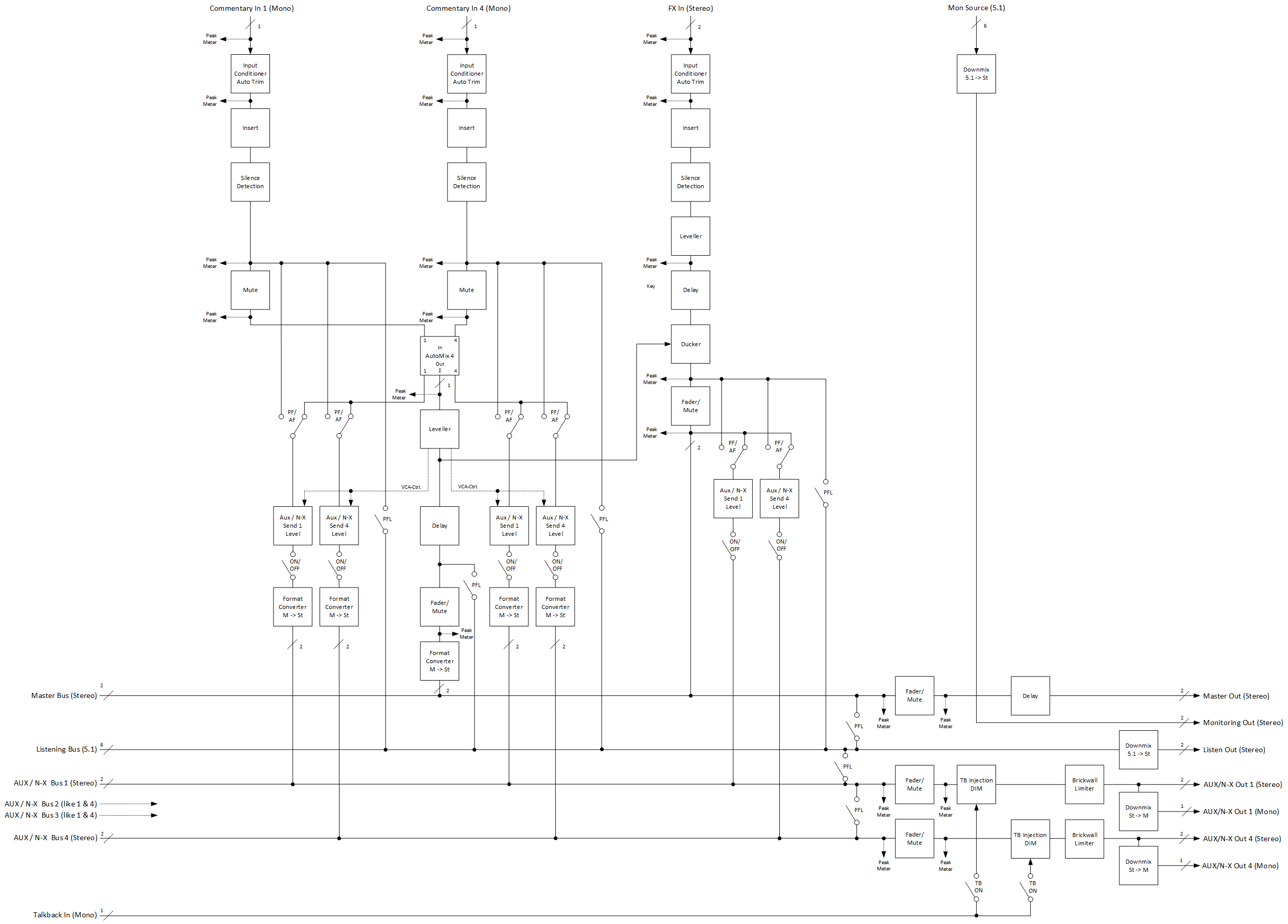
Stereo Voice-Over Process
The Stereo version of the Voice-Over Process is intended for broadcasters working only in Stereo.
It processes/mixes up to 4 mono Commentary voices with a stereo FX signal and mixes into a stereo Program-Out respectively a Stereo-Mix.
Each Commentator has its own N-X/AUX Master-Send, which can be used as an individual monitoring/IFB return channel.
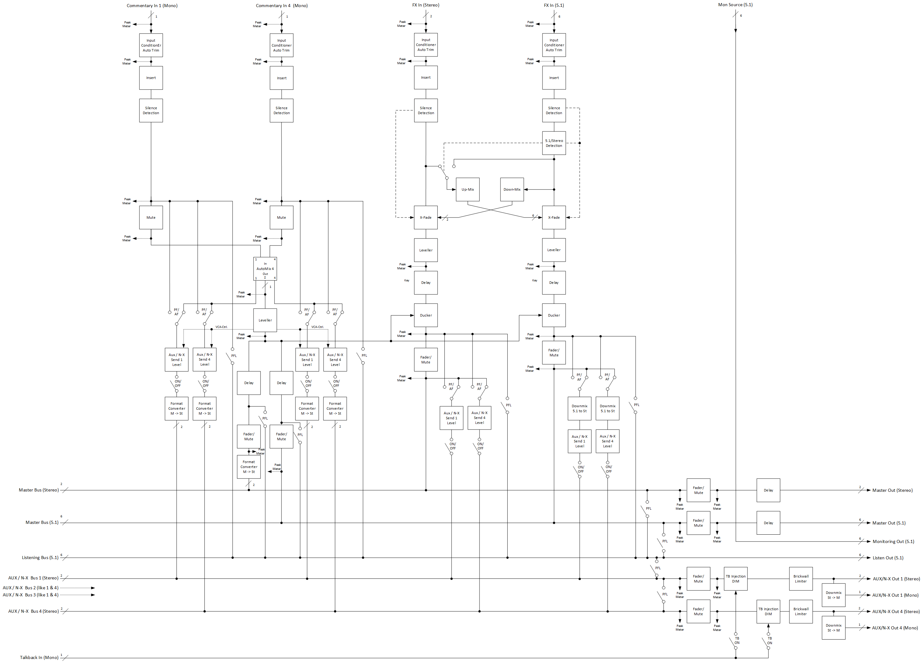
Stereo & 5.1 Voice-Over Process
The 5.1 version of the Voice-Over Process is intended for broadcasters working typically in 5.1 but alternatively also in Stereo or even both together (Simulcast).
It processes/mixes up to 4 mono Commentary voices, a stereo and/or a 5.1 FX signal and mixes into a stereo and/or a 5.1 Program-Out.
Each Commentator has its own N-X/AUX Master-Send, which can be used as an individual monitoring/IFB return channel.
Using the DSP Volume Activation
Activating an audio processing module
-
Select one DSP Volume item in the state qualified

-
Click on the

Deactivating an audio processing module
-
Select one DSP Volume item in the state active

-
Click on the