SAME supports a range of processing Applications, some of which are available as follows:
-
A plugin that can be applied to a signal.
-
An effect that is used within a mixer.
-
Both as a plugin and an effect where application configuration is similar but not exactly the same. In this case,the configuration for a mixer effect is used as the configuration example.
Signal Conditioner Plugin Effect Configuration
-
Typical Signal Conditioner Plugin for a Mixer (Stereo)
Failed to load the diagram preview image.
Authentication Required
Page ID: 1645412571
-
Typical Signal Conditioner Plugin for a Mixer (5.1)
Failed to load the diagram preview image.
Authentication Required
Page ID: 1645412571
The following configuration parameters may be available for the Signal Conditioner plugins.
|
Preset |
The configuration of a SAME Application can be memorized as a preset for instant recall. See SAME Application Preset Configuration. |
|
M/S Mode |
Click to set the signal conditioner’s output to Mono (mix left and right with the output available on all channels) or stereo. |
|
Trim |
Set the input gain for this channel to ensure there is sufficient signal without clipping. Click the knob and drag your mouse left to right to set the level. |
|
Ø |
Click to mute / unmute the leg’s input signal. |
|
Calibration |
Set the input gain for individual legs to offset any unequal signal levels. Click the knob and drag your mouse left to right to set the level. |
|
2 Channel Mode |
Set the current channel operating mode. LR Stereo: The left - right inputs are routed to the left - right outputs. RL Stereo Swapped: The stereo channels are swapped. The left - right inputs are routed to the right - left outputs. LL Left to L & R: Use the left channel only. The left input is routed to the left - right outputs. The right input is unused. RR Right to L & R: Use the right channel only. The right input is routed to the left - right outputs. The left input is unused. 2 Mono LR Sum: Mix the stereo inputs to make the signal mono on the left - right outputs. |
|
Peak Hold |
Click No hold: Shows sound levels. Transient peaks are not frozen. Temp hold: Shows sound levels while also freezing the display of the highest instantaneous peaks for a short period. Cont. hold: Shows sound levels while also freezing the display of the highest instantaneous peaks. Click RESET to clear the peak signal display on all level meters. |
|
Reset |
Reset the level meter's peak hold measurement. |
Insert / Return Plugin Configuration
Failed to load the diagram preview image.
Authentication Required
Page ID: 1645412571
The following configuration parameters may be available for the Signal Conditioner plugins.
|
Preset |
The configuration of a SAME Application can be memorized as a preset for instant recall. See SAME Application Preset Configuration. |
|
Send |
Shows the destination for the send signal. |
|
Return |
Shows the source for the return signal. |
|
UI Control |
Click to open open the UI of the inserted plug-in as a pop-up, to control the plug-in’s parameters. This option is available when a Network Plug-in is inserted in the channel-insert. |
|
Peak Hold |
Click No hold: Shows sound levels. Transient peaks are not frozen. Temp hold: Shows sound levels while also freezing the display of the highest instantaneous peaks for a short period. Cont. hold: Shows sound levels while also freezing the display of the highest instantaneous peaks. Click RESET to clear the peak signal display on all level meters. |
|
Reset |
Reset the level meter's peak hold measurement. |
Delay Plugin Effect Configuration
This plugin applies a time delay to the input signal. Delay times which are an integer number of the sampling period are supported.
Failed to load the diagram preview image.
Authentication Required
Page ID: 1645412571
|
Preset |
The configuration of a SAME Application can be memorized as a preset for instant recall. See SAME Application Preset Configuration. |
|
Delay Time |
Set the delay time to be applied to the audio signal. Click the knob and drag your mouse left to right to set the level. |
|
Time Units |
Set the amount of delay by units of time in milliseconds or seconds. |
|
Distance |
Set the amount of delay by units distance in feet or meters. |
|
Samples |
Set the amount of delay by samples at a given sample rate. |
|
Peak Hold |
Click No hold: Shows sound levels. Transient peaks are not frozen. Temp hold: Shows sound levels while also freezing the display of the highest instantaneous peaks for a short period. Cont. hold: Shows sound levels while also freezing the display of the highest instantaneous peaks. Click RESET to clear the peak signal display on all level meters. |
|
Reset |
Reset the level meter's peak hold measurement. |
High Pass / Low Pass Plugin Effect Configuration
Failed to load the diagram preview image.
Authentication Required
Page ID: 1645412571
|
Preset |
The configuration of a SAME Application can be memorized as a preset for instant recall. See SAME Application Preset Configuration. |
|
HP |
Shows the high-pass filter's cutoff frequency (-3 dB point). |
|
LP |
Shows the low-pass filter's cutoff frequency (-3 dB point). |
|
Frequency |
Set the filter's cut-off frequency. Click the knob and drag your mouse left to right to set the frequency. |
|
Slope |
Set the filter's cut-off slope. |
|
Peak Hold |
Click No hold: Shows sound levels. Transient peaks are not frozen. Temp hold: Shows sound levels while also freezing the display of the highest instantaneous peaks for a short period. Cont. hold: Shows sound levels while also freezing the display of the highest instantaneous peaks. Click RESET to clear the peak signal display on all level meters. |
|
Reset |
Reset the level meter's peak hold measurement. |
De-Esser Plugin Effect Configuration
Variants are available to support the following audio leg group types:
|
Mono |
Stereo |
5.1 |
|---|---|---|
|
|
|
|
The de-esser plugin performs dynamic range compression on selected frequencies to mitigate "s" like sibilance sounds.
Failed to load the diagram preview image.
Authentication Required
Page ID: 1645412571
Failed to load the diagram preview image.
Authentication Required
Page ID: 1645412571
|
Preset |
The configuration of a SAME Application can be memorized as a preset for instant recall. See SAME Application Preset Configuration. |
|
Frequency |
Set the filter's center frequency to act upon; where prominent sibilance sounds are heard. Click the knob and drag your mouse left to right to set the frequency. |
|
Filter Type |
Set the filter’s action. Peak: Use a notch filter to attenuate the excessive sibilance. Shelf: Use a low-pass filter to attenuate the excessive sibilance. |
|
Range |
Set the amount of allowable gain reduction, when this effect is triggered. |
|
Q-Factor |
Set the filter’s bandwidth or selectivity when set to Peak mode. |
|
Peak Hold |
Click No hold: Shows sound levels. Transient peaks are not frozen. Temp hold: Shows sound levels while also freezing the display of the highest instantaneous peaks for a short period. Cont. hold: Shows sound levels while also freezing the display of the highest instantaneous peaks. Click RESET to clear the peak signal display on all level meters. |
|
Reset |
Reset the level meter's peak hold measurement. |
Expander Gate Plugin Effect Configuration
Variants are available to support the following audio leg group types:
|
Mono |
Stereo |
5.1 |
|---|---|---|
|
|
|
|
This plugin performs dynamic range expansion and gating.
Failed to load the diagram preview image.
Authentication Required
Page ID: 1645412571
Failed to load the diagram preview image.
Authentication Required
Page ID: 1645412571
|
Preset |
The configuration of a SAME Application can be memorized as a preset for instant recall. See SAME Application Preset Configuration. |
|
Look Ahead Delay |
Set the amount of time the expander / gate is to track an audio signal for analysis ahead of time before applying gain correction to allow the expander / gate to respond to peaks precisely. This setting adds a corresponding processing delay. |
|
Expander: Threshold |
Set the inflection point below which quietening (gain reduction) dominates. Signals above this level pass through untouched. |
|
Expander: Range |
Set the lower inflection point where quietening of softer signals begin to take effect. |
|
Expander: Knee Width |
Set to soften the edges of Threshold and Range inflection point transitions. |
|
Expander: Ratio |
Set the gain reduction to be applied to a signal when falling below the Threshold level. A ratio of 2 applies a 2 dB output reduction for every 1 dB drop in input level below the threshold level. |
|
Gate: Threshold |
Set the level below which a signal is muted. |
|
Global: Speed |
Set the number of milliseconds before reacting to signal changes when the signal level is passing through a threshold. |
|
Global: Hysteresis |
Set to establish two new levels around each threshold. One level for a rising signal level and another level for a falling signal level. For example:
|
|
Preview |
Shows a preview of the effect on signal gain. E: Shows the inflection point where expansion dominates (Expander setting). R: Shows the inflection point where range dominates (Range setting). G: Shows the inflection point where gate threshold dominates (Threshold setting). |
|
Side Chain: High Pass Filter Frequency Low Pass Filter Frequency |
Set the frequency range used to detect sound energy levels that are used to control the expander / gate’s operation. Note that this effect does not modify the tonal balance of the input to output signal. Click the knob and drag your mouse left to right to set the frequency. |
|
Side Chain: High Pass Filter Slope Low Pass Filter Slope |
Set the filter's cut-off slope. |
|
Peak Hold |
Click No hold: Shows sound levels. Transient peaks are not frozen. Temp hold: Shows sound levels while also freezing the display of the highest instantaneous peaks for a short period. Cont. hold: Shows sound levels while also freezing the display of the highest instantaneous peaks. Click RESET to clear the peak signal display on all level meters. |
|
Reset |
Reset the level meter's peak hold measurement. |
Parametric Equalizer Plugin Effect Configuration
Variants are available to support the following audio leg group types:
|
Mono |
Stereo |
5.1 |
|---|---|---|
|
|
|
|
This plugin applies multiple filter sections (bands) to the input signal.
For each band we can select different filter types:
-
Highpass
-
Lowpass
-
Highshelf
-
Lowshelf
-
Peak
-
Notch
Failed to load the diagram preview image.
Authentication Required
Page ID: 1645412571
Failed to load the diagram preview image.
Authentication Required
Page ID: 1645412571
|
Preset |
The configuration of a SAME Application can be memorized as a preset for instant recall. See SAME Application Preset Configuration. |
|
Graph Range |
Set the range of the vertical axis. |
|
Frequency |
Set the filter's center frequency or cut-off frequency. |
|
Gain |
Set the amount of the filter’s signal gain. |
|
Q |
Set the filter's Q factor. Applies to Highshelf, Lowshelf. Peak, and Notch filter types. |
|
Slope |
Set the filter’s roll-off rate. Applies to Highpass and Lowpass filter types. |
|
Type |
Set the type of filter to use. Highpass: Affects frequencies above the filter’s cut-off frequency. Lowpass: Affects frequencies below the filter’s cut-off frequency. Highshelf: Affects frequencies above the filter’s cut-off frequency for broad tonal shaping. Lowshelf: Affects frequencies below the filter’s cut-off frequency for broad tonal shaping. Peak: A high selectivity filter that affects a relatively narrow-range of frequencies. Notch: A high selectivity filter that affects a very narrow-range of frequencies. |
|
Peak Type |
For a Peak filter type, set the filter’s profile. Constant Range: The filter acts on a range of frequencies regardless of the filter’s gain. Constant Q: The filter acts on a range of frequencies that vary according to the amount of filter gain. |
|
Preview |
Shows a preview of the filter's effect (Bode plot). 1 to 4: Shows the filter’s center frequency and gain level. |
|
Peak Hold |
Click No hold: Shows sound levels. Transient peaks are not frozen. Temp hold: Shows sound levels while also freezing the display of the highest instantaneous peaks for a short period. Cont. hold: Shows sound levels while also freezing the display of the highest instantaneous peaks. Click RESET to clear the peak signal display on all level meters. |
|
Reset |
Reset the level meter's peak hold measurement. |
Spectra-Match Plugin Effect Configuration
Variants are available to support the following audio leg group types:
|
Mono |
Stereo |
5.1 |
|---|---|---|
|
|
|
|
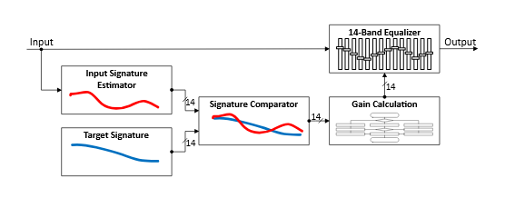
This performs dynamic filtering. It dynamically changes the spectral content of the signal to match a given spectral envelope. Spectra-Match permanently analyzes the frequency response of the incoming audio signal and filters it adaptively. The energy of a single band is only altered when necessary. This process steers 14 frequency bands individually to match a predefined response curve. This match curve can be captured as a ‘fingerprint’ (the signature) from a reference signal or it can be manually tweaked.
Failed to load the diagram preview image.
Authentication Required
Page ID: 1645412571
The algorithm is equivalent to the renowned Jünger Spectral Signature Plugin.
Failed to load the diagram preview image.
Authentication Required
Page ID: 1645412571
|
Preset |
The configuration of a SAME Application can be memorized as a preset for instant recall. See SAME Application Preset Configuration. |
|
Frequency bands |
Select and configure the adaptive filtering for each of the 14 frequency bands. |
|
Global Settings:
|
In order to achieve a stable and natural behavior, the intensity of the gain change needs to be processed according to a response curve. This curve is defined by a ratio. A high ratio means that a difference of 5 dB results in a gain change of almost the same amount. A low ratio means that the actual gain applied is lower. A ratio of 2:1 would bring the amplification up to 2.5dB in this example. The max gain value is applied after the ratio calculation. As these ratios are not static, they have been combined into three preset responses. The average ratio increases from 'Soft' to 'Hard'. |
|
Global Settings:
|
This parameter controls the time taken for the bands to reach their target values, shown below in relative order: slow to fast. Fast settings even out differences between sources, but can lead to audible transitions. They are well suited for single channel signals, for example to even out sound differences due to movement in front of a microphone. Slower settings remain unobtrusive, but cannot bring down differences very quickly. They are suitable for mixed content or buses with varying content. The overall spectrum remains well balanced without drastic sonic changes.
|
|
Global Settings:
Global Settings:
|
To prevent a band from amplifying noise (especially hum), a relative gate can be set. If the energy within one frequency band is lower than this gate, no amplification will take place. This is especially useful, when mixed content with highly varying frequency response is processed (for example a radio station output with alternating presenter voice and music). When enabled, the suggested setting is from -10 to -24 dB. |
|
Global Settings:
|
Set behavior to adopt during a signal absence. Release: In continuous operation the Low Level Mode' should remain in 'Release'. In this case the dynamic gain slowly returns to its neutral state in case of signal absence. In this mode a returning signal would start a new processing period with its lead in attack time. Hold: The Release mode may not be appropriate in production applications where transport operations introduce unnatural gaps. In these cases, the Hold mode will pause the dynamic processing at the last value until the signal returns. Returning signals are treated just like continuous signals to keep processing fluent over moments of signal loss. |
|
Band:
|
Absolute processing gate threshold for the selected frequency band. Signals below this threshold are silenced. |
|
Band:
|
Target Signature level for the selected frequency band. |
|
Band:
|
Maximum Gain that can be applied in the selected frequency band. |
|
Signature |
Spectra-Match is a dynamic filter tool to even out differences between signals from different sources or of different condition. It does not have an absolute reference. Only if the incoming signal's frequency response equals the reference response (signature), will Spectra-Match will operate in a neutral manner. To create a reference spectrum, or 'Signature', apply a program signal on the input which represents the signature you want to create; this is then converted into a new Signature. Failed to load the diagram preview image. Authentication Required Page ID: 1645412571 |
|
Peak Hold |
Click No hold: Shows sound levels. Transient peaks are not frozen. Temp hold: Shows sound levels while also freezing the display of the highest instantaneous peaks for a short period. Cont. hold: Shows sound levels while also freezing the display of the highest instantaneous peaks. Click RESET to clear the peak signal display on all level meters. |
|
Reset |
Reset the level meter's peak hold measurement. |
Compressor / Limiter Plugin Effect Configuration
Variants are available to support the following audio leg group types:
|
Mono |
Stereo |
5.1 |
|---|---|---|
|
|
|
|
The performs dynamic range compression.
Failed to load the diagram preview image.
Authentication Required
Page ID: 1645412571
Failed to load the diagram preview image.
Authentication Required
Page ID: 1645412571
|
Preset |
The configuration of a SAME Application can be memorized as a preset for instant recall. See SAME Application Preset Configuration. |
|
Look Ahead Delay |
Set the amount of time the compressor / limiter is to track an audio signal for analysis ahead of time before applying gain correction to allow the compressor / limiter to respond to peaks precisely. This setting adds a corresponding processing delay. |
|
Compressor: MakeUp Gain |
MakeUp gain is typically used to restore a signal’s level after compression has reduced it. Disabled: Apply no makeup gain to the signal after compression. Manual: Apply a fixed amount of gain / reduction to the compressor’s output. Auto: Allow the compressor to automatically calculate the amount of makeup gain to apply to the compressor’s output to approximate the input level, within the maximum set by MakeUp Range. |
|
Compressor: MakeUp Range |
Set the amount of makeup gain headroom allowed when MakeUp Gain is set to Auto. |
|
Compressor: MakeUp Gain |
Set a fixed amount of makeup gain when MakeUp Gain is set to Manual. |
|
Compressor: Threshold |
Set the rotation point level. Not to be confused with threshold, this parameter defines the turning point of the response curve from upward to downward compression. When set to 0dBFS, the signal is only amplified according to the ratio and range settings. |
|
Compressor: Ratio |
Set the Compressor’s slope. This determines the amount of gain reduction by applying a ratio. A ratio of 2 applies a 1 dB output gain for every 2 dB increase in input level above the rotation point. |
|
Compressor: Upward Range |
This defines the range over which upward compression is applied as defined by the ratio setting. Signals outside of this range are still amplified but not altered in their dynamic structure. |
|
Compressor: Soft Knee Knee Width |
Set to soften the edges around the rotation inflection point transition. |
|
Compressor: Speed |
The timing characteristics of the compressor are generated adaptively according to the incoming signal structure. The overall timing can be set up from fast and responsive settings (lower numbers) to relaxed settings (higher numbers) without detailed access to the actual micro timings. |
|
Compressor Preview |
Shows a preview of the effect on signal gain. C: Shows where compression dominates, where the slope is controlled by the Ratio setting. R: Shows the rotation point level. |
|
Limiter: Threshold |
Soft Limiter threshold. Point at which Limiter will be fully working (knee applied before this level) |
|
Limiter: Soft Knee Knee Width |
Set to soften the edges around the threshold inflection point transition. |
|
Limiter: Release |
Release time setting. 0 is for a fast release, and 1 is for a very slow release behavior. |
|
Side Chain: High Pass Filter Frequency Low Pass Filter Frequency |
Set the frequency range used to detect sound energy levels that are used to control the compressor / limiter’s operation. Note that this effect does not modify the tonal balance of the input to output signal. Click the knob and drag your mouse left to right to set the frequency. |
|
Side Chain: High Pass Filter Slope Low Pass Filter Slope |
Set the filter's cut-off slope. |
|
Peak Hold |
Click No hold: Shows sound levels. Transient peaks are not frozen. Temp hold: Shows sound levels while also freezing the display of the highest instantaneous peaks for a short period. Cont. hold: Shows sound levels while also freezing the display of the highest instantaneous peaks. Click RESET to clear the peak signal display on all level meters. |
|
Reset |
Reset the level meter's peak hold measurement. |
K-Leveller Plugin Effect Configuration
Variants are available to support the following audio leg group types:
|
Mono |
Stereo |
5.1 |
|---|---|---|
|
|
|
|
This performs automatic adjustment of the perceived loudness level to match a predefined target value. The algorithm is a lightweight version of the Level Magic (no true peak meter, no gated loudness measurement).
Failed to load the diagram preview image.
Authentication Required
Page ID: 1645412571
Failed to load the diagram preview image.
Authentication Required
Page ID: 1645412571
|
Preset |
The configuration of a SAME Application can be memorized as a preset for instant recall. See SAME Application Preset Configuration. |
|
Operating Mode |
Set the signal detection algorithm’s operating mode. Level (dBFS): Calculates loudness based on quasi-peak level detection. K-Leveller meters are in dB. Loudness (LKFS/LUFS): Calculates loudness based on ungated integrated loudness measurement. K-Leveller meters are in LU. The Input Level and Output Level meters will be fed with peak or loudness values accordingly. |
|
Leveller: Gain [level meter] |
Shows the amount of gain currently being applied to the signal due to the K-Leveller’s action. |
|
Leveller: Target level |
Set the:
ITU has defined the unit of measure to be LKFS (loudness K-Weighted referenced to digital Full Scale; these are the preferred units in USA/Canada). EBU has defined the unit of measure to be LUFS. Note: LKFS and LUFS are different units for the same measure. They are fully compatible. |
|
Leveller: Speed |
Set the K-Leveller Time, that is how fast it tries to reach target level. This controls the speed at which K-Leveller tries to reach target level. This setting should not be confused with the attack time of a conventional sound processor. As the leveling process is a self-adjusting system this time is not an absolute term but rather an initial value that could exceed the numerical value many times. When setting it, it is necessary to take the overall function of the system into account. Production duties may require faster time settings, while ingest or play-out correction systems may need slower settings. |
|
Leveller: Freeze Level |
Set the level where the K-Leveller holds the amount of gain or attenuation when the signal level drops below this threshold. It works in a similar way to a Hold function in other sound processors. For example: Assuming the process applies a gain change of 10 dB to achieve target loudness, the input level will suddenly drop below freeze level. The gain change remains in its last state until the signal returns above Freeze Level. This behavior is different to the Min Threshold (see below) where the gain change would return to its neutral state if the level falls below Min Threshold. It is necessary to always set Freeze Level above the Min Threshold to prevent unwanted release behavior. |
|
Leveller: Max Gain |
Set the maximum permitted gain change to reach the target level. It can be useful to limit the maximum amount of gain so as not to overly boost noise and other unwanted signals. The maximum attenuation is not affected by this setting. The system regulates the maximum attenuation adaptively to the signal structure. |
|
Leveller: Min Threshold |
Set the level below which the K-Leveller is not active. |
|
Leveller: Below Threshold |
Set the K-Leveller’s behavior when the signals falls below the Min Threshold level. Hold: All internal states are kept as is. When the signal returns, the K-Leveller continues where it left off. Release: The internal states are reset. Clear History: Click to clear the processing history. This can be used when the program content changes. |
|
Transients: Profile |
Set the general characteristics of Level Magic’s response through one of five presets. These presets affect the timing of the Transient Processor and also its ratio. See also the Transient Processor Response below. Live: fastest response, Speech: fast response, Pop: medium response, Universal: slow response, Classic: slowest response |
|
Transients: Max Gain |
Set the Transient Processor’s maximum processing gain range. Sometimes a hard Response setting with a very limited gain range can sound more natural than a softer response at full gain range. Adjusting the Transient Processor according to the designated overall behavior of the K-Leveller process will improve its neutral processing character. |
|
Transients: Response |
Set how the K-Leveller responds to program transients. Soft: A relaxed response to program transients that provides a less aggressive levelling of transients (more lively). Mid: An intermediate response to program transients. Hard: A strong response to program transients that provides a more aggressive levelling of transients (more relaxed). The response of the Transient Processor continuously self-adjusts to adapt to the incoming signal structure. Its response and the underlying compression ratio can be adjusted with these three presets from a more lively to a more relaxed setting, but it also depends on the Profile setting. This means that the overall handling of transients and peaks is determined by the parameters of the Transient Processor and K-Leveller. The following picture illustrates this interaction between the Transient Processor Response and Leveler Processing Profile, depending on the parameter settings: 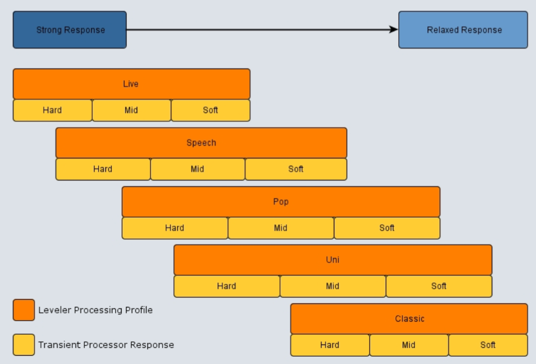
|
|
Transients: Auto Boost |
Response Boost is a function that temporarily increases the Transient Processor’s reaction intensity. It raises the compression ratio by a factor of 1.5 for more effective control of signal sections that lie above the target loudness level. For all other signals below the target level, the nominal Response parameter settings will be applied. Response Boost is intended to be a temporary function that allows users to apply relatively conservative Level Magic settings for normal operation, and to rapidly increase the processing parameters at the point of transition to a potentially louder than target section (e.g. movie to commercial break). This feature can be triggered either through loading a preset, a parameter event from an external trigger (GPI, Automation) or manually through a button within the Web UI. It can be triggered once or held on for as long as required. After the trigger is released, the ratio slowly returns back to its nominal value over a period of approximately 10 seconds. Please note that when triggered by loading a preset, Response Boost is fired once and then released immediately. To hold the function on for a longer period, it must be triggered through a Parameter Event. |
|
Loudness [level meter]: In |
Shows the:
|
|
Loudness [level meter]: Out |
Shows the:
|
|
Peak Hold |
Click No hold: Shows sound levels. Transient peaks are not frozen. Temp hold: Shows sound levels while also freezing the display of the highest instantaneous peaks for a short period. Cont. hold: Shows sound levels while also freezing the display of the highest instantaneous peaks. Click RESET to clear the peak signal display on all level meters. |
|
Reset |
Reset the level meter's peak hold measurement. |