
Topology Simulation
Overview
Topology Simulation represents the physical installation as Nodes and Links in hi. The Topology model is used for Signal Path tracing, Tally propagation, Dynamic Labels, metadata transport, and topology-aware routing checks.
Here, simulation means calculating signal relationships from the installation model and device routing state. It is not a separate practice environment or Hardware Panel simulator.
Start with Nodes and Layers for the objects represented in this model.
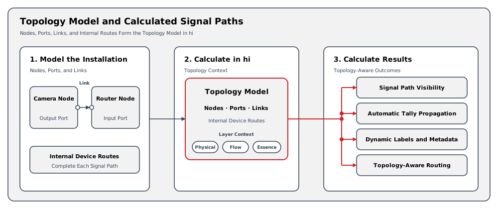
Configured Nodes, Wiring, and internal device routes supply the model used to calculate Signal Paths and related behavior.
Nodes and Links
Most of the devices in a media or production installation can be represented by a Node in hi. Creating links between the Ports of these Nodes represents the physical interconnections between these devices.
The Topology is built by adding relevant Nodes and creating the Wiring between these Nodes in hi. A wire (or link) connects an output Port of a Node to an input Port of another Node. All Nodes and their wires form the system Topology.
Signal Paths
Using Nodes, Ports, Wiring, and device routing state, the hi system can calculate the relevant Signal Path for a signal.
Signal Path tracing is the foundation for:
-
Automatic Tally propagation - Tally is evaluated across the relevant rooted Signal Path (see Tally and Labels).
-
Dynamic Labels - label text can be calculated from the signal origin and sent to configured targets.
-
Metadata transport - key-value pairs follow their configured propagation rules.
The Topology Diagram
The Topology View visualizes Nodes, Ports, and Wiring. It also provides the supported workflow for editing Wiring and saving diagram views.
The view can present the Physical, Flow, or Essence Layer. See Layers for the meaning of each Layer and View and Edit Topology for filters, views, export, and Wiring procedures.
Example: Follow a Camera Through a Router
A camera output is wired to a router input. The Wiring describes that device-to-device connection; the router's current routing state identifies its internal connection.
Together, those relationships let the hi system calculate the camera's Signal Path through the router. Configured Tally and Dynamic Label behavior use that path.
An operator can Inspect a Signal Path to identify the originating Source and downstream devices.
The inspector presents an Essence Layer trace and does not edit the Topology or change routing.
Operational Implications
The calculated path depends on the configured Wiring and device routing state. An incomplete model can omit relationships needed to understand Tally or label behavior.
Inspect the path before changing configuration. Use Topology editing only when the modeled Wiring needs correction and your account has the required access.
Related Tasks and Reference
-
Inspect a Signal Path - review the calculated path without modifying it.
-
View and Edit Topology - inspect Layer views and maintain modeled Wiring.
-
Tally and Labels - understand the behavior that uses Signal Paths.
-
Layers - distinguish Physical, Flow, and Essence relationships.