
Signal Routing Reference
Overview
This reference defines the hi signal model and routing behavior. It covers the three Layers, routing entities, and Signal Paths. Use it to understand how Ports, Port Containers, and Portals participate in routing.
For topic-specific introductions, see Layers, Port Containers, and Portals.
How hi Models Signals: Three Layers
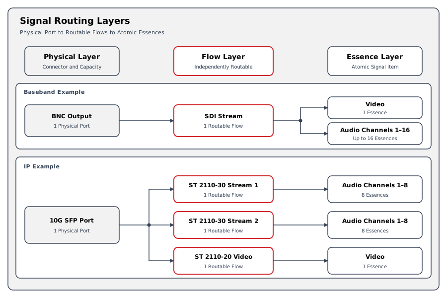
hi models every installation on the Physical, Flow, and Essence Layers. Routing happens at the Flow Layer, where Port Containers and Portals also operate, and Tally is associated with Essence Ports. See Layers for the model.
Ports
A Flow Port represents one routable signal on a Node. A Flow Port can carry multiple Essences. Operators connect a Source to a Destination, and the hi system resolves the corresponding routing entities.
|
Attribute |
Description |
|---|---|
|
Direction |
Input
|
|
Format Type |
The signal format carried by this Port
|
|
Medium |
Baseband or IP |
A Port belongs to a Node. The Node can represent a physical device, software service, or logical component.
Format Types
The format type determines what kind of signal a Port carries and enforces compatibility rules during routing.
|
Category |
Type in the Interface |
Description |
|---|---|---|
|
Baseband |
SDI |
Serial Digital Interface |
|
Baseband |
Audio |
Analog or digital audio |
|
Baseband |
GPIO |
General Purpose I/O |
|
Baseband |
Data |
Generic data |
|
Network |
NDI |
NDI network video |
|
Network |
AMPP Stream |
GV AMPP streaming format |
|
SMPTE IP |
ST2022-8 |
ST 2022-6 streams synchronized within an ST 2110-10 system |
|
SMPTE IP |
ST2110-20 |
Uncompressed video over IP |
|
SMPTE IP |
ST2110-30 |
Audio over IP (AES67) |
|
SMPTE IP |
ST2110-40 |
Ancillary data over IP |
|
Compressed |
Compressed V |
Compressed video stream |
|
Compressed |
Compressed A |
Compressed audio stream |
|
Compressed |
Compressed D |
Compressed data stream |
Connection rule: Two Ports can only connect if their format types match exactly (for example, SDI to SDI or Audio to Audio). Mismatched formats are blocked.
Information
Note that the format type describes the Flow Layer transport, not the essences inside. An SDI Port and an ST 2110-20 Port both carry video, but they use different transports and cannot be directly connected without conversion.
Port Containers
A Port Container is a named, ordered group of Ports that acts as a single routing entity. See Port Containers for the model and Audio Shuffling for reordering slots at routing time.
Key Attributes
|
Attribute |
UI Label |
Description |
|---|---|---|
|
Slots |
Setup Container Contents |
An ordered list of Port assignments (positions start at 1) |
|
Flow Direction |
Source Container / Destination Container |
Whether this container provides or receives signals |
|
Template |
Template |
Optional reference to a Port Container Template for structure enforcement |
Display names: Port Containers use the Primary, Panel, Monitoring, and Mixer Name fields defined in Nodes: Naming.
Behavioral settings:
|
Setting |
Effect |
|---|---|
|
Show Parameters From Ports |
Surfaces parameters from contained Ports onto the Control Panel |
|
Disconnect Destination Ports On Replacing This Source |
Disconnects destination Ports that do not match when this Source Container is replaced |
Slots
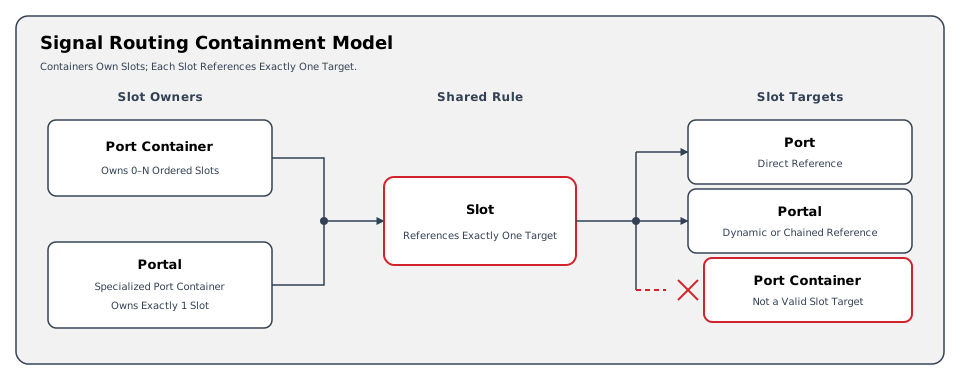
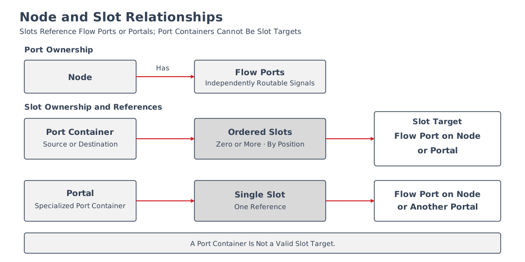
A Slot is a single position within a Port Container. Each slot has a position number (starting at 1) and a format type. A slot references either:
-
A Flow Port on a Node (direct reference) - the standard case
-
A Portal (dynamic reference) - the slot resolves to whatever Port the Portal currently wraps
Slots are shown in the hi web interface under Setup Container Contents when editing a container. Operators move Ports from the available Port list into the container and arrange them.
Port Container Templates
Templates define a Port Container's structure as a set of slot definitions before any real Ports are assigned. They allow standardized container layouts (for example, "4x SDI + 2x Audio") that enforce consistent structure across the system.
|
Property |
Purpose |
|---|---|
|
Slots |
List of slot definitions specifying expected positions and format types |
|
Connect Matching Templates Only |
When enabled, routing requires the matching Port Container Template |
Portals
A Portal is a specialized Port Container that manages exactly one slot. It acts as a virtual, named routing point - an indirection layer that decouples operator workflows from physical infrastructure.
Portal States
A Portal is always in one of three states:
|
State |
Description |
|---|---|
|
Assigned to Port |
Wraps a specific Flow Port on a Node. The Portal resolves to that Port's signal and format. |
|
Assigned to Portal (chaining) |
Linked to another Portal. Linking copies that Portal's current assignment; reassigning the referenced Portal later does not update this Portal. |
|
Unassigned |
Not connected to anything. Ready for assignment. |
See Portals for Portal connections, chaining, loop detection, Portals inside Port Containers, and access and licensing requirements.
Containment Rules
What Can Be Inside What
|
Relationship |
Allowed? |
Notes |
|---|---|---|
|
Port inside a Port Container |
Yes |
Standard use case
|
|
Port inside a Portal |
Yes |
A Portal's single slot wraps one Port |
|
Portal inside a Port Container |
Yes |
A slot can reference a Portal for dynamic resolution |
|
Portal inside a Portal (chaining) |
Yes |
One Portal's slot references another Portal |
|
Port Container inside a Portal |
No |
A Portal holds exactly 1 slot; it can only point to a Port or another Portal |
|
Port Container inside a Port Container |
No |
Slots reference Ports or Portals, not other containers; no recursive nesting |
Nesting Diagram
Connection and Routing
How Routing Works
When an operator connects a Source to a Destination - whether individual Ports, Port Containers, or Portals - hi creates a routing record at the Flow Layer that tracks the connection through its lifecycle.
Connection sides:
-
Source: A Source Container, a Portal, or a single Port
-
Destination: A Destination Container, a Portal, or a single Port
Connection Lifecycle
Routing a connection moves through three phases:
|
Phase |
Description |
|---|---|
|
1. Requested Routes |
All Port pairs the operator requested to connect |
|
2. Routes That Changed |
The subset that actually needed to change (already-routed pairs are excluded) |
|
3. Confirmed Routes |
Routes that the controlled device reports as applied |
These phases distinguish the requested route set from the routes that changed and the routes confirmed by controlled devices.
Connection Status
In the Control Panel's Port Container status view, slot indicators use the labels Connected, Connected but shuffled, Not connected, Pending connection, or Connection not possible. A single container can show more than one slot status.
Connection Rules
-
Format type matching - Two Ports can only connect if their format types match exactly.
-
Port Container pairing - In the Connect Port Containers dialog, Source and Destination rows pair by displayed row number. Drag either set of rows to change the mapping before taking the route; the default order maps Slot 1 to Slot 1, Slot 2 to Slot 2, and so on.
-
Template enforcement - If Connect Matching Templates Only is enabled, routing requires matching Port Container Templates.
-
One connection per destination - Only one active Source connection per Destination at a time. Connecting a new Source replaces the previous one.
Updating Connections After Container Changes
When a Port Container is edited, select Save and update connections to apply its changed Port assignments to live routes that use it. The editor also has a Save action; saving the definition alone does not request this connection update.
A Portal assignment can affect routes through Port Containers that reference it. Review the affected routing after changing a Portal or its assignment.
Signal Path
The Signal Path represents the route from an originating Source through connected Nodes to Destinations. Flow Layer routing records describe requested and confirmed routes. The Signal Path Inspector displays the calculated trace at the Essence Layer. These are different views of the signal model.
How Signal Paths Are Built
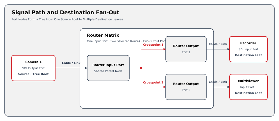
Each Port is represented as an entry in the Signal Path tree. Connections between Ports create parent-child relationships. The tree represents the following connection types:
|
Component |
Description |
|---|---|
|
Cable / Link |
A connection between Ports on different devices (physical cable or IP stream) |
|
Crosspoint |
An internal switching point within a device (for example, a route set on a router matrix) |
Signal Path Structure
A single Source can fan out to multiple Destinations through the Signal Path tree. Each Destination is a leaf node.
Tally and Label Propagation
Caution
Tally calculation begins at Ports that report a Tally state. The hi system resolves the relevant rooted Signal Path and applies the Tally result to the affected Essence Ports. Labels and other Metadata follow their configured propagation and target rules. Do not assume that they follow Tally in the same direction.
Each Layer contributes different information to Tally calculation:
-
Physical Layer: which devices are connected.
-
Flow Layer: which signals are switched and where.
-
Essence Layer: which audio channel or video quadrant is active.
Putting It All Together
The following diagram relates the Flow Layer routing entities to Signal Paths and propagation:
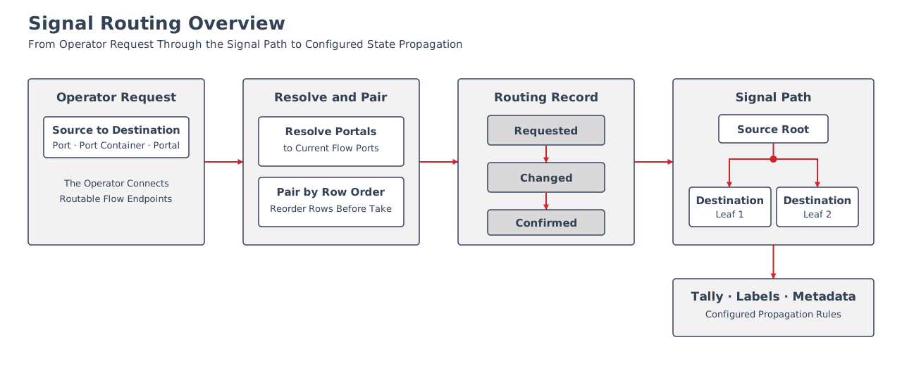
The flow from operator action to signal delivery:
-
Operator routes a Source Port Container to a Destination Port Container (or connects Portals, or connects individual Ports)
-
hi resolves any Portal references to their current Flow Ports
-
In Connect Port Containers, Source and Destination rows pair by displayed row order. Drag rows to change the mapping before taking the route; format type matching still applies.
-
Routing Record is created with requested, changed, and confirmed route phases
-
Signal Path tree is updated, establishing parent-child relationships between Ports
-
Tally, labels, and Metadata are evaluated using their configured propagation rules and the updated Signal Path
Quick Reference: Routing Model
Use the Glossary for term definitions. This table distinguishes the routing entities from the displayed Signal Path.
|
Concept |
What It Represents Here |
Layer |
|---|---|---|
|
Physical Port |
A connector on a device (BNC
|
Physical |
|
Flow Port |
A routable signal on a Node
|
Flow |
|
Essence |
An atomic signal item (one audio channel
|
Essence |
|
Port Container |
A named group of Ports that routes as a single entity |
Flow |
|
Slot |
A position within a Port Container holding a Port or Portal reference |
Flow |
|
Portal |
A virtual routing point that wraps one Flow Port or chains to another Portal |
Flow |
|
Template |
A slot layout definition for creating standardized Port Containers |
Flow |
|
Cable / Link |
A connection between Ports on different devices |
Flow |
|
Crosspoint |
An internal switching point within a device |
Flow |
|
Signal Path |
The calculated route displayed by the Signal Path Inspector |
Essence in the inspector |
|
Tally |
Operational status associated with Essence Ports and evaluated across relevant Signal Paths |
Essence |
Constraints
-
Routing occurs at the Flow Layer and follows the format, row-order, template, and Destination rules in Connection Rules.
-
Portals resolve to one Flow Port or another Portal. Port Containers cannot contain other Port Containers.
-
Device-specific routing behavior and network ports are described on the Supported Integration pages.
Related Procedures
-
Layers - detailed explanation of the Physical, Flow, and Essence Layers
-
Port Containers - conceptual introduction to grouped routing entities
-
Portals - conceptual introduction to virtual Sources and Destinations
-
Tally and Labels - how Tally propagates through Signal Paths
-
Route a Source to a Destination - apply a route
-
Inspect a Signal Path - review the read-only Essence Layer trace
-
Manage Port Containers - create and manage Port Containers
-
Manage Portals - create and assign Portals