
View and Edit Topology
Overview
Select Diagram from the navigation panel to open the Diagram workspace. It renders devices as Nodes and their physical or logical connections as links. Use it to inspect wiring, plan Signal Paths, and save changes to the system.
Prerequisites
Viewing the diagram requires the Wiring Diagram access role. Confirm the selected Layer and maintenance window before saving Wiring changes.
Information
See also: Concepts: Topology Simulation for Signal Paths, Layers, and Tally propagation.
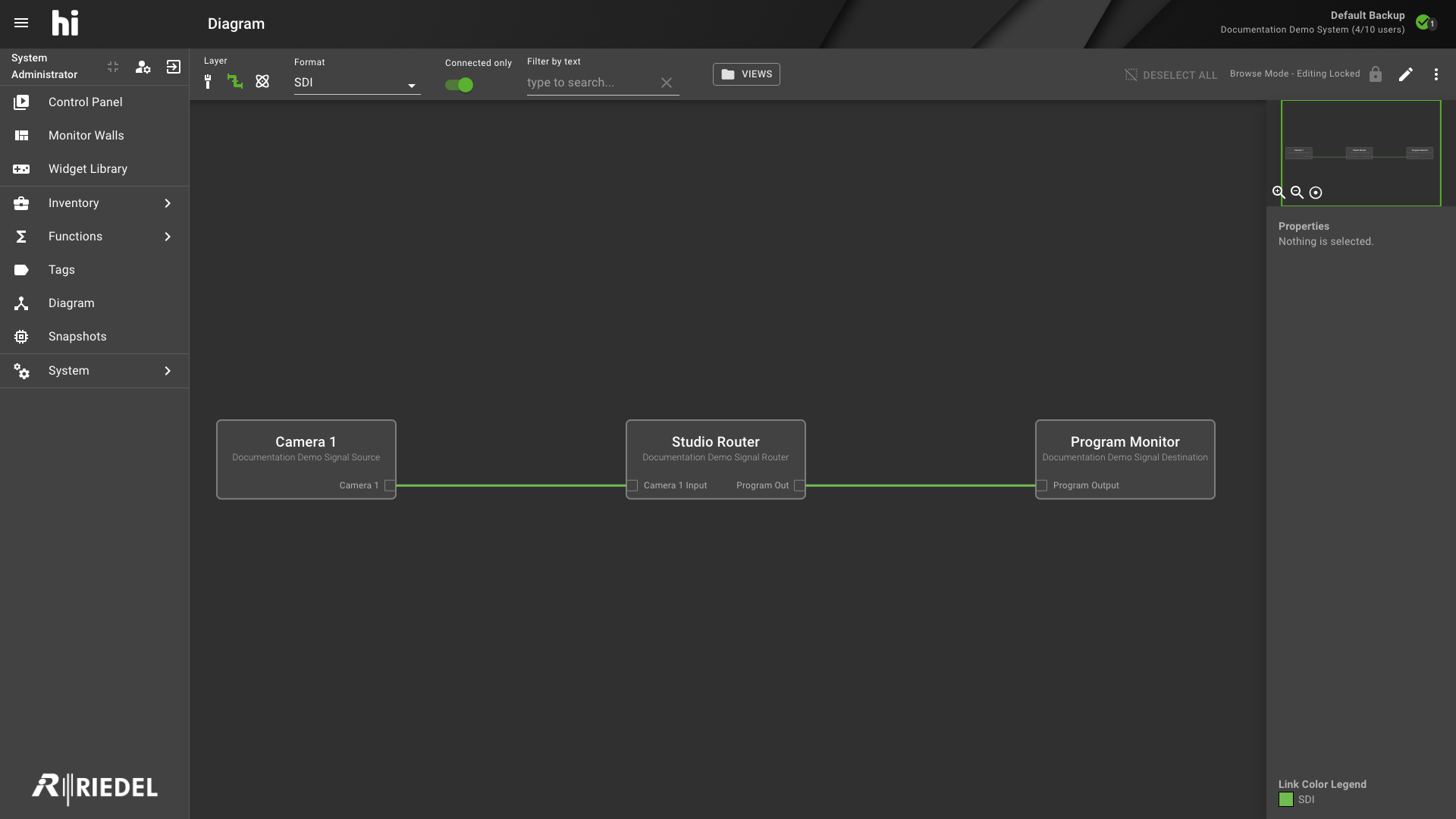
Navigating and Filtering in the Diagram
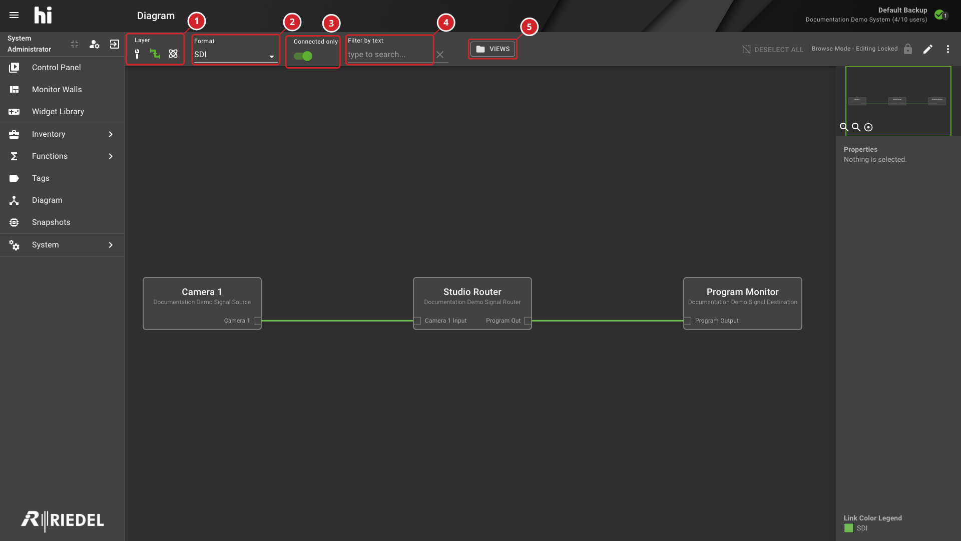
The filter bar spans the top of the diagram canvas and controls which data is visible.
-
Select Layer to switch between Physical, Flow, and Essence views.
-
Select Format to filter Ports and links by signal format.
-
Enable or disable Connected only to show only wired Ports or all matching Ports.
-
Enter a value in Filter by text to highlight Nodes by name, manufacturer, or product name.
-
Select VIEWS to save or recall a diagram configuration.
|
Control |
Description |
|---|---|
|
Layer |
Switch between Physical, Flow, or Essence Layer. Each Layer exposes a different set of Ports and links. Changing the Layer reloads all diagram data for the selected Layer. |
|
Format |
Filter Ports and links by signal format. The available options depend on the selected Layer (for example, SDI, Audio, GPIO, Data, and Ethernet on Physical; Video, Audio, and Ancillary on Essence). Select All to remove the format filter. |
|
Connected only |
Shows only wired Ports (default).
Connected Ports Only |
|
Filter by text |
Highlights Nodes whose name, manufacturer, or product name contains the search text. Other Nodes remain visible. Clear the field to remove the highlights. |
|
VIEWS |
Open the VIEWS bar to store and recall diagram configurations.
Using Views |
|
Deselect All |
Clear the current selection of Nodes, links, and Ports. Disabled when nothing is selected. |
|
Browse / Edit toggle |
Switch between Browse Mode (read-only) and Edit Mode (wiring enabled).
Editing a Diagram |
|
More menu (three-dot icon) |
Access additional actions: Reset Pagination, Export as PNG, Export as SVG, and (where available) switch to Table View. |
Minimap and Zoom
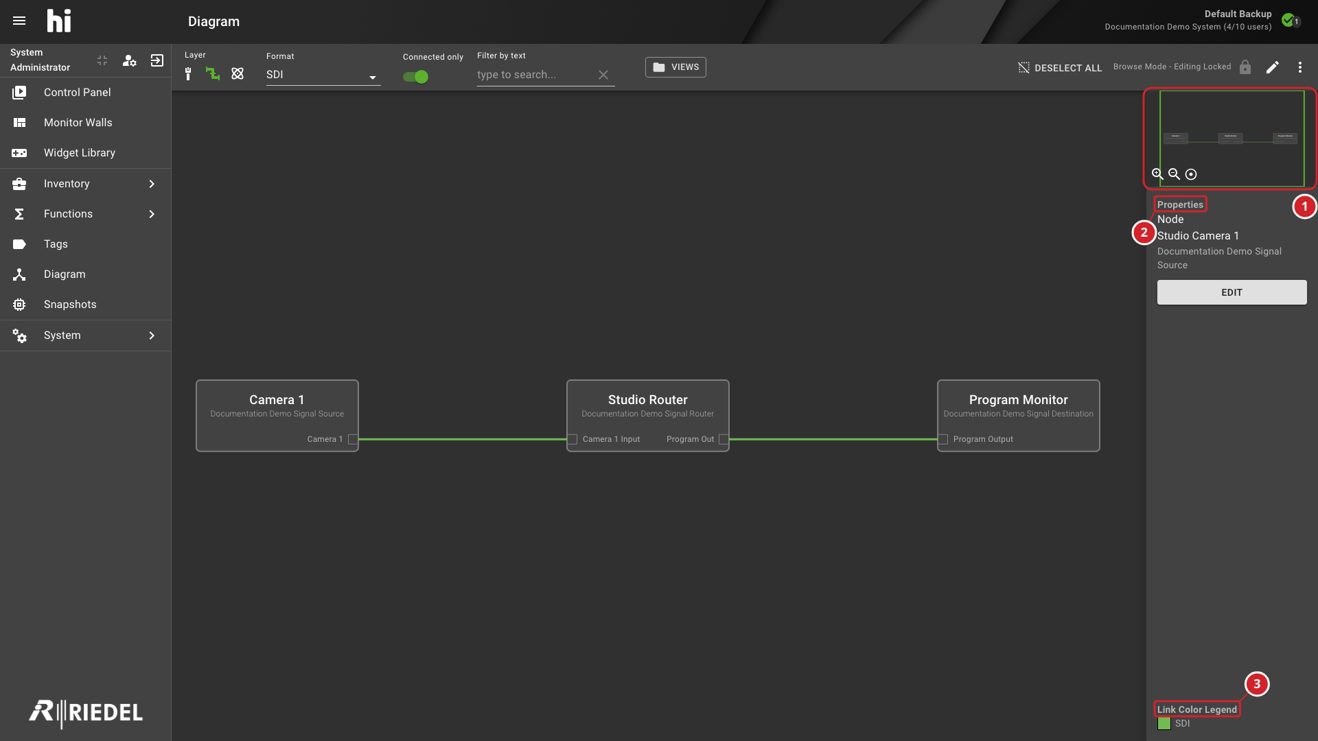
The sidebar on the right side of the diagram contains an overview minimap that shows the entire diagram at a reduced scale. The highlighted rectangle within the minimap indicates the currently visible viewport.
Below the minimap, three controls are available:
|
Control |
Action |
|---|---|
|
Zoom In |
Increase the diagram scale. |
|
Zoom Out |
Decrease the diagram scale. |
|
Zoom Reset |
Restore the diagram to its default scale and position. |
Use the mouse scroll wheel to zoom in and out directly on the canvas. Select and drag on an empty area of the canvas to pan.
-
The minimap shows the diagram overview and the visible viewport.
-
Properties identifies the panel containing details about the selection.
-
Link Color Legend explains the colors used for links.
Pagination
When a device Node contains a large number of Ports, the diagram paginates them automatically. Navigation arrows appear on the Node to step through pages of Ports. Select Reset Pagination from the More menu to return all paginated Nodes to page one.
Using Views
A view captures the complete state of a diagram: Node positions, zoom level, pan position, the selected Layer, signal format filter, and the Connected Only toggle. Views allow rapid switching between different perspectives of the same system.
-
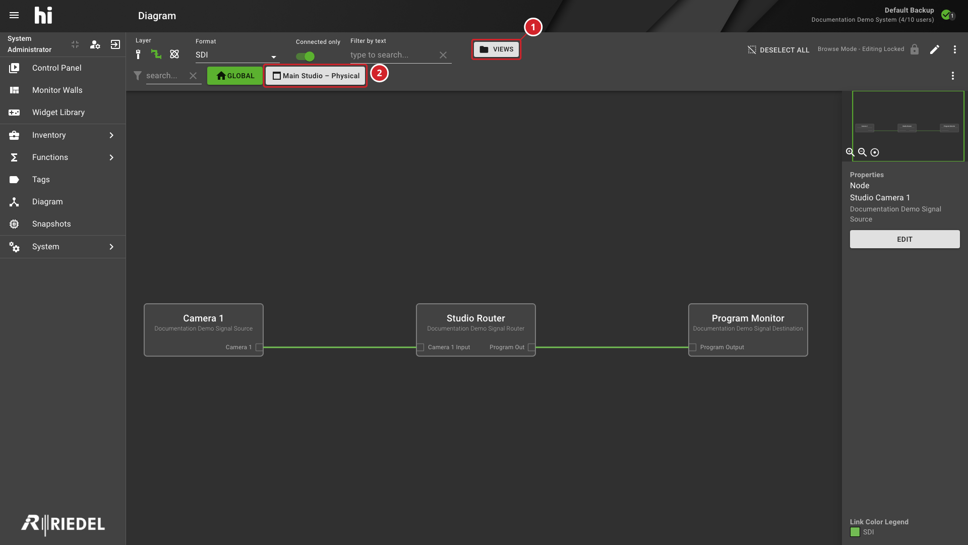
VIEWS opens or closes the saved Views bar.
-
Select a saved View to recall its diagram configuration.
Managing Saved Views
The VIEWS bar provides selection and management of existing saved Views. It does not provide a command for creating a new View.
-
Open the VIEWS bar and select an existing View.
-
Use Update current preset to save the current diagram settings, or Edit current preset to open the selected View's settings.
-
Use Delete current preset only when the shared View is no longer needed.
See Recalling a View, Updating a View, and Deleting a View for the corresponding procedures.
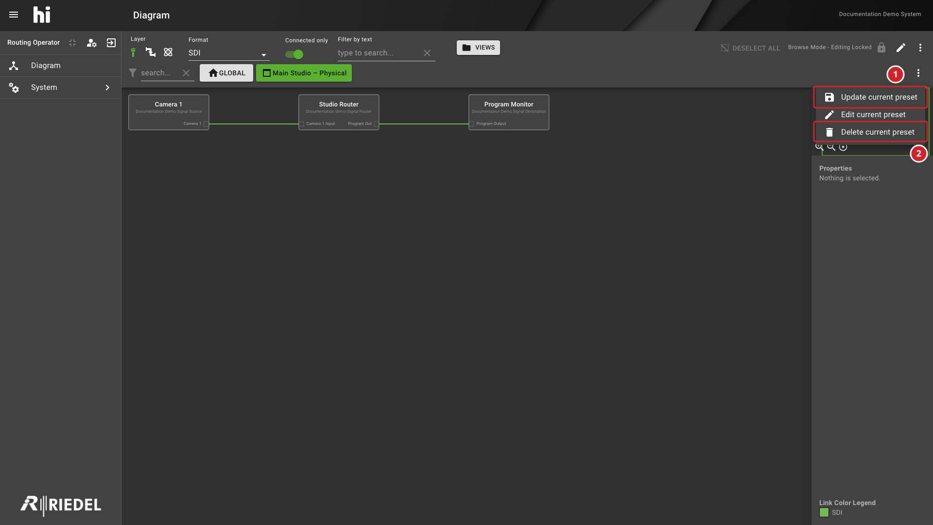
-
Update current preset opens the update confirmation for the selected View.
-
Delete current preset opens the deletion confirmation for the selected View.
Recalling a View
-
Open the VIEWS bar by selecting the VIEWS button.
-
Select the saved view entry. The diagram reloads with the stored Node positions, zoom level, and filter settings.
When navigating back to the Diagram page during the same session, the most recently recalled view is restored automatically.
Updating a View
-
Recall the view to update.
-
Make adjustments (reposition Nodes, change filters).
-
Select Update current preset in the VIEWS bar settings menu, then confirm Update. The stored configuration is replaced with the current state.
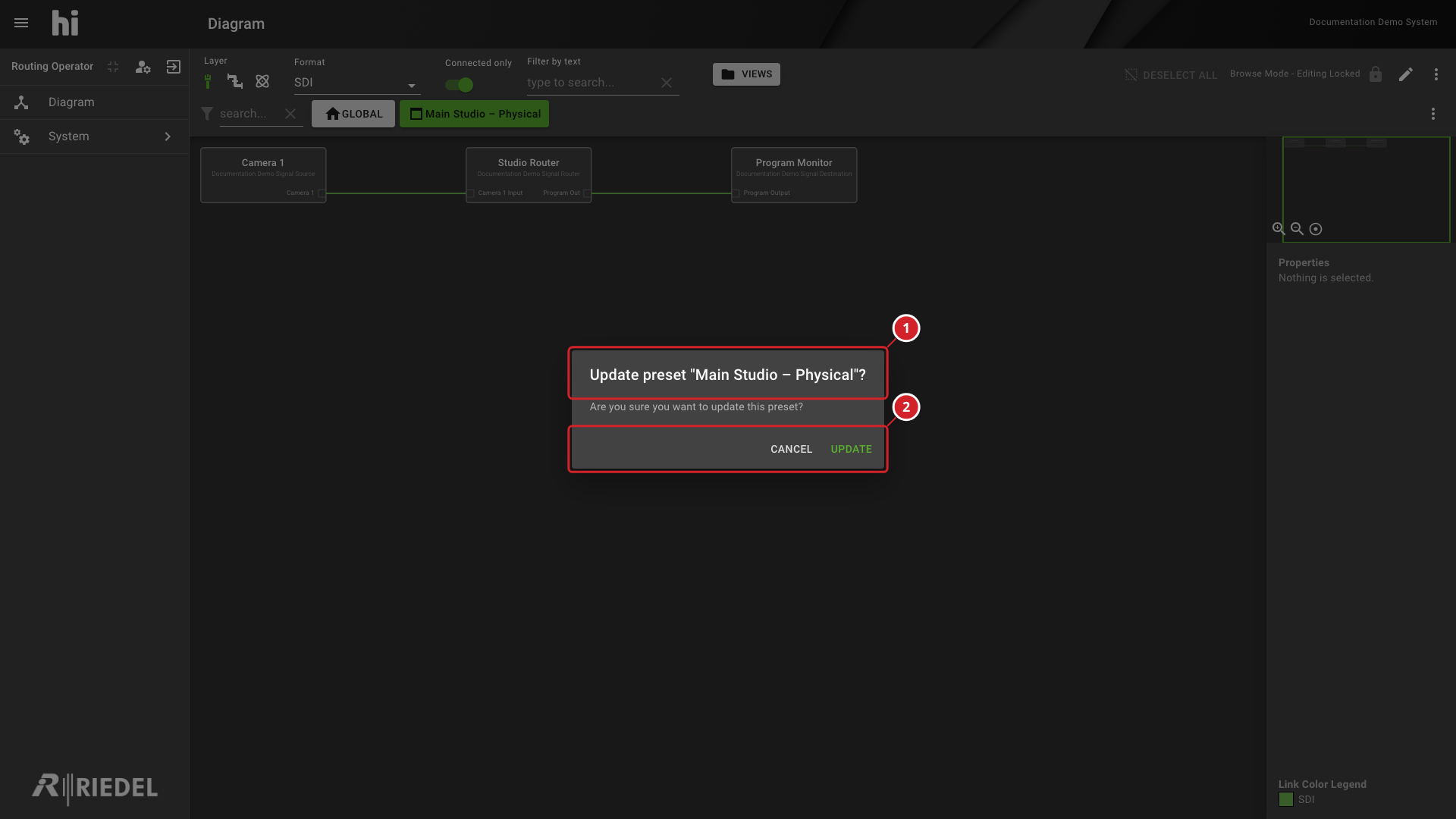
-
The confirmation names Main Studio – Physical as the View to update.
-
Select Update to confirm, or Cancel to close the dialog.
Deleting a View
Views are shared across all users with the Wiring Diagram access role assigned.
Caution
Deleting a view removes it for all users. Confirm that the view is no longer needed before deleting it.
-
Open the VIEWS bar.
-
Select Delete current preset in the VIEWS bar settings menu.
-
Select Delete to confirm. The view is permanently removed.
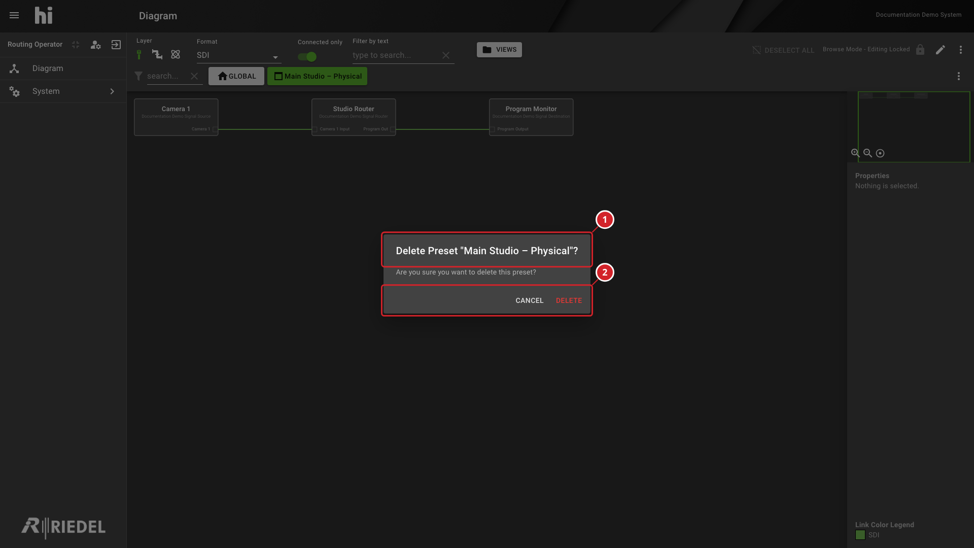
-
The confirmation names Main Studio – Physical as the View to delete.
-
Select Delete to confirm, or Cancel to keep the View.
Editing a Diagram
See Edit Wiring in the Diagram.
Layer Selection Strategy
The Layer selector determines which abstraction level of the signal topology is displayed. Each Layer serves a distinct operational purpose.
Information
See also: Concepts: Layers for the full Layer model.
|
Layer |
Shows |
Use When |
|---|---|---|
|
Physical |
Physical connectors and cables (BNC, RJ45, fiber, and other connectors) with format types such as SDI, Audio, GPIO, Data, and Ethernet. |
Documenting the physical cabling infrastructure. Verifying which Physical Ports are connected. Troubleshooting cable-level issues. |
|
Flow |
Routable signals carried over baseband or IP transports. Format types include SDI, Audio, NDI, AMPP Stream, ST2022-8, ST2110-20, ST2110-30, ST2110-40, and the compressed media formats. |
Inspecting routable SDI, audio, or IP signals and router Crosspoints. Validating NMOS or ST 2110 Flow paths. |
|
Essence |
Logical signal content (Video, Audio, Ancillary Data) independent of transport. |
Inspecting individual video, mono audio, or ancillary content along a Signal Path. Verifying Tally propagation paths. |
Select the Layer that matches the current task. Physical represents connectors and cables, Flow represents routable transport signals, and Essence represents individual signal components.
Connected Ports Only
The Connected only toggle (enabled by default) filters out all Ports that have no wires attached. This reduces visual clutter on large systems where many Ports are provisioned but not yet cabled.
Disable this toggle when:
-
Planning new wiring and needing to see all available unconnected Ports.
-
Auditing Port utilization across devices.
-
Troubleshooting connections expected in the Topology but not shown.
When the toggle is off, every Port matching the current Layer and signal format filter is displayed, including those with zero connections.
Export
The diagram can be exported as a static image for documentation, reports, or offline review. Export options are accessible from the More menu (three-dot icon) in the filter bar.
|
Format |
Description |
|---|---|
|
Export as PNG |
Downloads a raster image of the current diagram viewport. |
|
Export as SVG |
Downloads a vector image of the current diagram viewport. SVG scales without raster quality loss. |
The exported file name defaults to the active view name (for example, Studio-A-Physical.png). If no view is selected, the file is named diagram.png or diagram.svg.
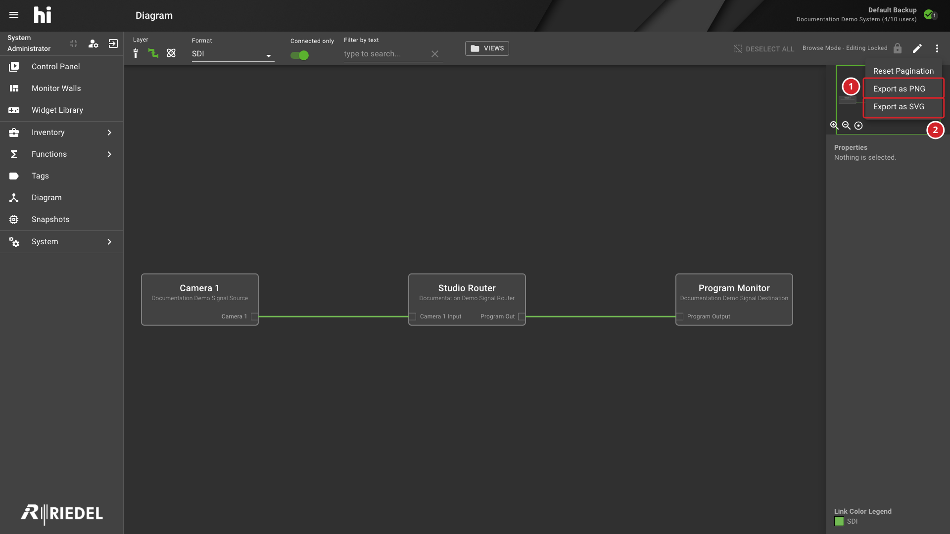
-
Export as PNG downloads a raster image.
-
Export as SVG downloads a vector image.
Sidebar Selection Details
When a Node or link is selected on the canvas, the sidebar displays contextual information:
-
Node selected: Device name, manufacturer, product name, and an Edit link to the Node administration page.
-
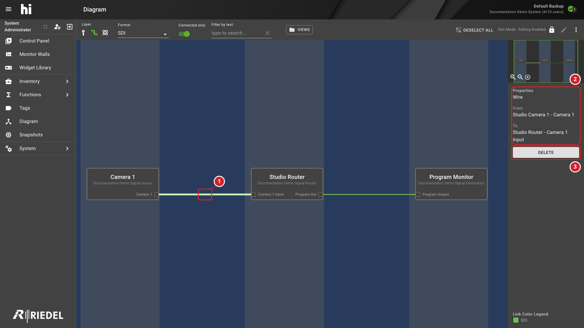
Link selected: Source and Destination device and Port names under From and To, and a Delete action that is disabled in Browse Mode.
-
Port selected: Port name, direction, medium, format type, Tags, and connected link details.
The sidebar also provides a link to navigate directly to the selected device's administration page.
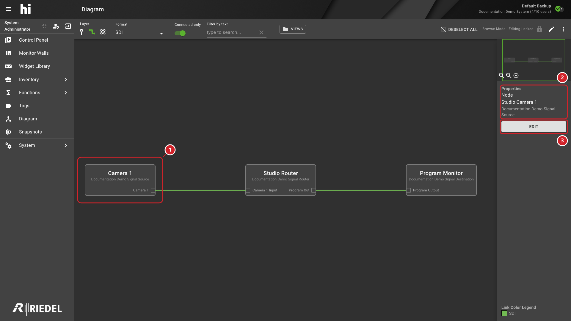
-
The selected Node identifies the device being inspected.
-
Properties shows information about the selected Node.
-
Select Edit to open the Node's administration page.
Verify the Result
After saving Wiring changes, leave Edit Mode and confirm that the affected link remains visible. Trace the expected Signal Path at the required Layer before returning the installation to service.
Related Procedures
-
Use Manage Nodes to inspect the affected Node configuration.
-
Use Control Panel to verify routing through the saved Topology.
Task Illustrations
For the procedure, see Edit Wiring in the Diagram.
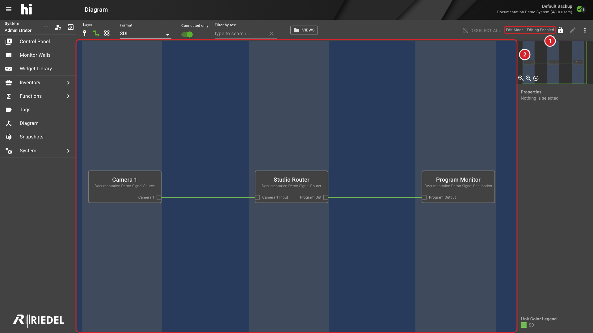
Diagram in Edit Mode with the Editing State and Striped Canvas Annotated
-
Edit Mode - Editing Enabled confirms that Wiring changes can be made.
-
The striped canvas identifies the diagram being edited.
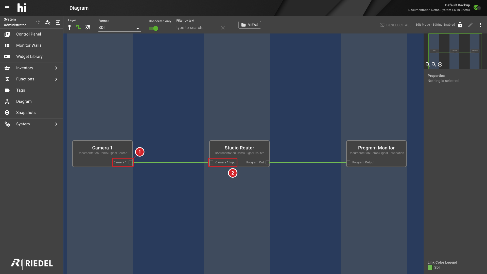
Diagram with the Output and Input Connectors Used to Create a Wire Annotated
-
Start at the Source output connector.
-
Drag to the Destination input connector to create the wire.
Selected Wire Sidebar Showing Its Endpoints and Queued Deletion Action
-
The selected wire connects the highlighted Source and Destination Ports.
-
Properties shows the selected wire's endpoints.
-
Select Delete to queue removal of the wire.
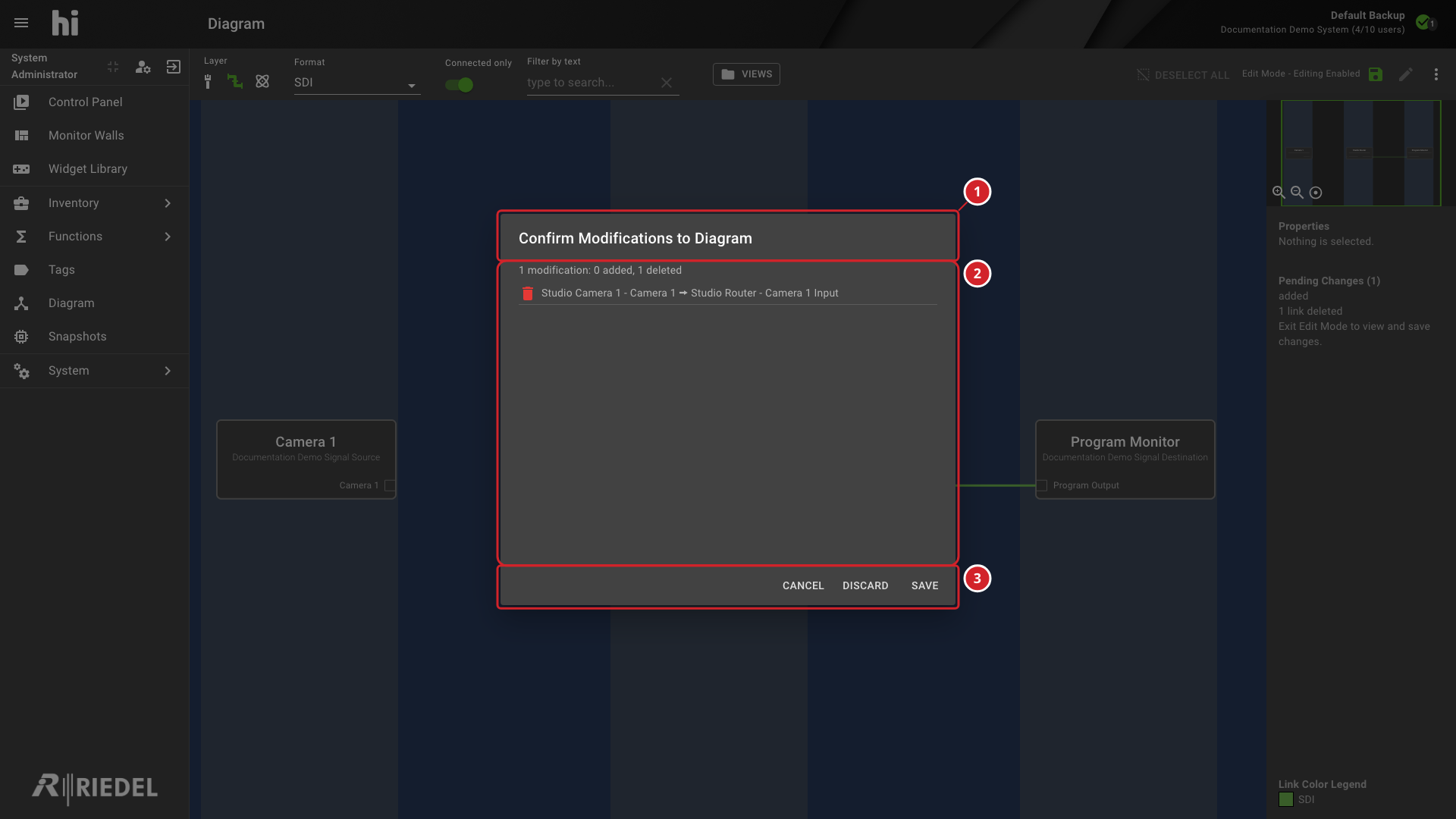
Diagram Confirmation Dialog Showing a Pending Wire Deletion and Save Controls
-
The confirmation dialog identifies the pending diagram modifications.
-
The summary counts added and deleted wires.
-
Select Save to apply the changes, Discard to abandon them, or Cancel to continue editing.