
Inspect a Signal Path
Overview
Trace a Port's signal through the system topology without changing the routing.
Prerequisites
-
Use an account with Control Panel access and Tag access to the required Sources and Destinations.
-
Open Control Panel and select the required Preset.
-
Leave Customize, Gang Take, and other editing modes. The inspect action is disabled in those modes.
Open the Inspector
-
Select a Port on the Control Panel.
-
Select Inspect Selected Port/Port Container in the Port list toolbar.
-
Review the path summary and diagram.
The inspector is also available from the Node edit view's Labels tab through the Signal Path icon beside a Port.
Signal Path Diagram
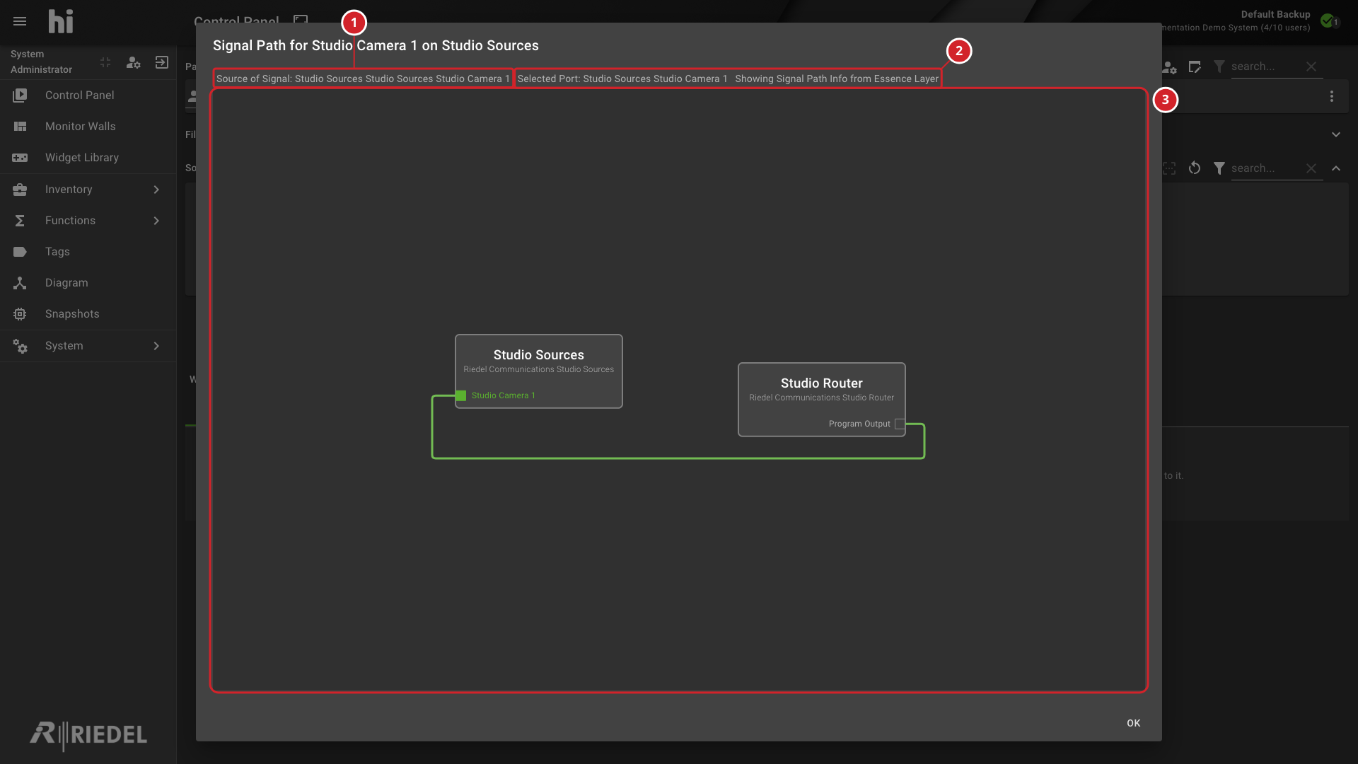
The inspector displays an interactive diagram containing:
-
Device nodes - each device in the Signal Path is represented as a Node showing the device name and its relevant Ports.
-
Links - connections between devices are drawn as links between output and input Ports.
-
Port labels - each Port on a Node displays its name and direction (input, output, or bidirectional).
Information
The diagram is read-only and cannot be edited.
Signal Path Information
Above the diagram, the inspector displays:
|
Field |
Description |
|---|---|
|
Source of Signal |
The root device and Port where the signal originates (for example, a camera output) |
|
Selected Port |
The Port that was inspected to open this view |
Loop Detection
The inspector states Showing Signal Path Info from Essence Layer. If a signal routes back to its origin, it shows LOOP DETECTED AT in red, followed by the device and Port where the loop occurs.
Behavior
-
A loading indicator appears while the Signal Path is retrieved.
-
The view traces the selected Port back to the root Source and forward through downstream devices.
-
The diagram presents the path at the Essence Layer.
-
Source of Signal identifies the originating device and Port.
-
The summary identifies the selected Port and the Essence Layer.
-
The diagram shows the Signal Path between the Source and Destination devices.
Verify the Result
Confirm the originating Source, selected Port, and displayed Essence Layer path. If LOOP DETECTED appears, review the routing loop in the Topology.
Next Steps
Return to the Use the Control Panel task list.