
Nodes
Overview
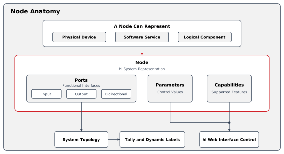
A Node represents a physical device, software service, or logical component within a hi installation. Ports describe the interfaces and signals exposed by that Node.
A Node consolidates the capabilities of a device into a single system model. This representation is used for:
-
Topology-based Tally calculation - hi traces Signal Paths across Nodes to determine where Tally information should be propagated.
-
Dynamic Labels - Source names can follow signals through the configured Topology when supported by the connected devices.
-
Consistent control - parameters, routing, and monitoring for supported devices are accessible from the hi web interface.
Ports
The Ports of a Node describe input, output, or bi-directional interfaces. These can be physical input or output connectors of a device or endpoints of a service. Ports can be interconnected using a link, which can represent a physical cable between the Ports of two devices.
Naming
Each Port can expose four operator-facing label fields and one name reported by the device:
|
Name |
Description |
|---|---|
|
Primary Name |
The main name of the Port. It is used in the hi web interface on computers and tablets. It has no length limitations. |
|
Monitoring Name |
This name is sent to Multiviewers and UMDs. By default, this name is empty and inherits its content from the Primary Name. |
|
Panel Name |
This name is limited to 10 characters and is used on Hardware Panel buttons. When a Node is created, the Panel Name is automatically generated from the Primary Name using a shortening algorithm. |
|
Mixer Name |
This name is sent to vision mixers as Source information. By default, this name is empty and inherits its content from the Panel Name. |
|
Original Name |
The name reported by the connected device, shown as Name from Device in the Port list and available as a Label Override. |
Layers
Ports exist on the Physical, Flow, and Essence Layers. See Layers for the Port Layer model.
Formats
Depending on the Layer, a Port can have different formats. Formats determine compatibility between Ports. The following format types are available:
Essence Layer
|
Format |
Description |
|---|---|
|
Video |
A single-channel video signal. |
|
Audio |
A single mono channel of audio. |
|
Ancillary |
Ancillary (ANC) data. |
Flow Layer
Flow Layer format types include baseband formats (such as SDI, Audio, GPIO, and Data), network formats (such as NDI), SMPTE IP formats (such as ST 2110-20), and compressed formats. See Signal Routing Reference for the complete format-type table, including descriptions and connection rules.
Physical Layer
|
Format |
Description |
|---|---|
|
SDI |
SDI connector. |
|
Audio |
Audio connector. |
|
GPIO |
GPIO connector. |
|
Data |
Data connector. |
|
Ethernet |
Ethernet connector. |
Capabilities
A capability describes which features of the device are available for control in hi and which protocols are used to execute this capability. Examples of capabilities include:
-
Crosspoint Management
-
Parameter Control
-
UMDs
Wiring of Nodes
Wiring between Nodes forms the system Topology. See Topology Simulation for the Wiring and Topology model.
Operational Implications
For example, a router Node exposes its input and output Ports and supported Crosspoint Management capability. Operators route between those Ports using the Control Panel. The configured Wiring relates the router to other Nodes for Signal Path inspection and Tally calculation.
The Node model does not establish support for every feature of the connected device. Use its Supported Integration page to confirm available capabilities and limitations.
Related Tasks and Reference
-
Use Manage Nodes to view, filter, and administer Nodes.
-
Use Route a Source to a Destination to route supported Ports.
-
Use Inspect a Signal Path to trace the signal across Nodes.
-
See Layers for the relationship between Physical, Flow, and Essence Ports.