
Manage Nodes
Overview
The Node List shows all device representations of the current configuration.
Prerequisites
Open Inventory > Nodes. The page requires hiCore for new orders, or hiBase for an existing hiBase installation, a normal licensed session, and the Node admin role.
Node Overview
The Nodes page displays all devices that can be controlled by the system. From this page, a Node admin can add new devices and change or delete existing Nodes.
Every Node in the Nodes list is displayed with its name and an icon. The list also shows the assigned Tags, the Tally information, the IP addresses and Port settings, and the Connection State.
Integration-Specific Node Details
Node fields and routing behavior can vary by integration. Use the canonical NMOS Core Integration page for NMOS-specific behavior and license requirements. Use the matching Integrations page for other device-specific settings.
NMOS Multicast Range Validation
For range validation and the networks and ranges procedure, see Manage Multicast Addresses.
Operations in the Node List
Link Panels
Select Link Panels to group multiple panels. The group acts as a single panel in the hi system.
Filter Nodes
Filter for Node Names or Tags by entering the name.
Selection
-
Select - select all visible Nodes.
-
Deselect - deselect all Nodes.
-
Reselect - restore the previously selected Nodes.
Assigning Tags
Select one or more Nodes, select Assign Tag, and add or remove Tags.
Deleting Nodes
Caution
Deleting the selected Nodes removes them from the system for all users. Confirm that they are no longer required before deleting them.
Select Delete to remove the selected Nodes.
Adding Nodes
Adding Nodes from Templates
hi provides templates for commonly used devices. Select a Node Family and template, then use Direct Create to configure its capabilities. Select Save to return to the cart, then select Create Nodes. For a guided example, see Add Your First Device.
Information
Can't find a template? Try a generic template (for example, "Pro-Bel SWP08 compatible Router") or contact your Riedel representative to discuss template availability.
Adding Auto-Discovered Nodes
If hi has discovered devices on the network, they appear in the Auto-Discovered Nodes section.
Editing a Node
Select a Node and select the edit icon to open the detail view. Depending on the Node type, different tabs are available.
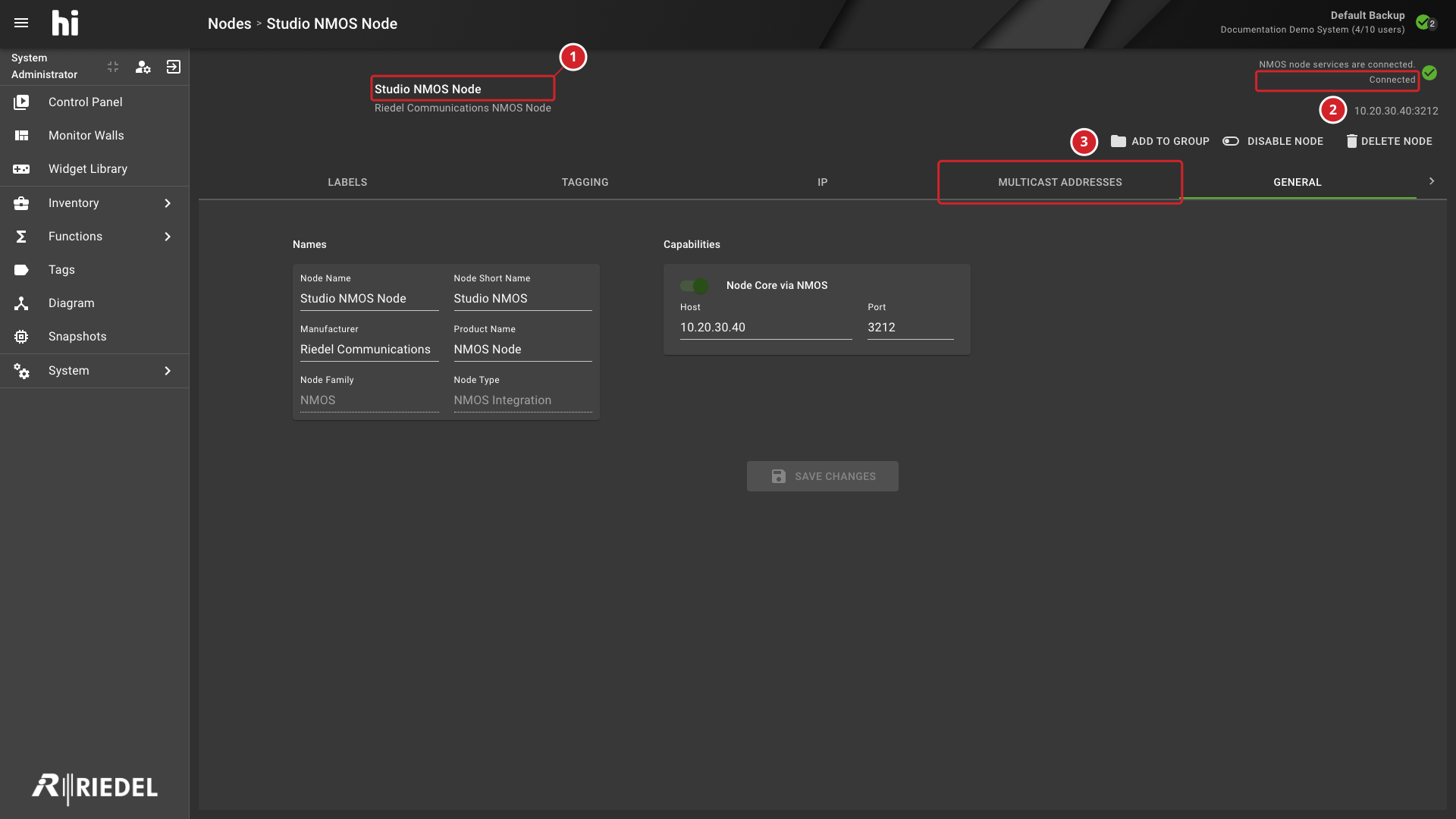
-
Studio NMOS Node identifies the selected Node.
-
Its reported Connected state.
-
Select Multicast Addresses to open its management controls.
Node Configuration Tabs
The tabs of a Node depend on the Node type, its capabilities, and your roles. The detail view shows only the tabs that apply, in the order below. General is always the last tab and is available on every Node. When you open a Node without a tab selected, hi opens Ports for a GPIO Node that has Ports, Labels for another Node that has Ports, and General for a Node without Ports.
|
Tab |
Appears When |
See |
|---|---|---|
|
Ports |
The Node has the GPIO capability and has Ports. It replaces Labels and Tagging. |
GPIO Nodes |
|
Labels |
The Node has Ports and no GPIO capability, or the Node has the Node Core capability, such as an NMOS Node. |
Common Options: Labels |
|
Tagging |
Same as Labels. |
Port Tagging |
|
IP |
The Node has at least one visible IP Port that is not internal, or the Node has the Node Core capability. It does not appear on a Node with the Compressed Routing capability. |
IP Tab |
|
Multicast Addresses |
The Node is the NMOS integration Node. |
Manage Multicast Addresses |
|
IP mapping |
At least one Port of the Node is mapped to an IP Port. |
IP Mapping Tab |
|
Routes |
The Node has the Crosspoint Management capability. |
Direct Routing |
|
Dynamic Labels |
The Node has the Dynamic Labels capability and it is enabled. |
Dynamic Label Setup |
|
Wiring |
The Node has Ports. |
Wiring |
|
Node |
The Node is a Hardware Panel, or it is a hiDot with the hiDot capability enabled. |
Configure hiDot |
|
Panel Group Setup |
The Node is a Panel Group, which is a Hardware Panel that has child panels. |
Configure Panel Groups |
|
UMD Settings |
The Node has the UMD capability. |
Configure UMD Labels |
|
Matrix Assignment |
The Node has the Northbound capability. |
Matrix Assignment |
|
Tallies |
The Node has the Crosspoint Management or IP Transceiver capability, or the Tally Provider capability. |
Tallies from Router Outputs |
|
Parametric Dynamic Labels |
The Node has the Parameter Control capability. On a hiDot, the capability must also be enabled. |
Parametric Dynamic Labels |
|
Parameters |
The Node has the Parameter Control capability and it is enabled. |
Parameter Control Nodes |
|
Storage |
The Node has the Video Server capability. |
Video Server Players and Storage |
|
Players |
The Node has the Video Server capability. |
Video Server Players and Storage |
|
General |
Always. |
General Options |
A tab that does not appear is not available for that Node. For example, a Node without Ports shows no Labels, Tagging, or Wiring tab.
Common Options: Labels
The Labels tab shows all Ports and their names. Filter by direction, Layer, format, or text. The editable labels are Primary Name, Monitoring Name, Panel Name, and Mixer Name. Name from Device is read-only. See Nodes: Naming for their definitions.
-
Rename a Port - select an editable label field to edit inline
-
Batch-rename - select multiple Ports and use search/replace with optional counter
-
Export/Import - download as XLSX, edit, and upload back
Additional Port Operations
Select Ports and use the three-dot menu for additional operations:
-
Show Port Numbers - toggle display of Port index numbers
-
Export Port Labels to file - create an XLSX containing Ports and their labels for bulk editing
-
Import Port Labels from file - apply the names and Port numbers from an edited XLSX. Ports that are missing from the file are not removed.
-
Create new Ports on this Node - add Ports manually for Node types that support user-created Ports.
-
Create Port Container - create a new Port Container from selected Ports
-
Create Snapshot - store the labels and Tag assignments of selected Ports in a Snapshot
-
Change Format Type - modify the signal format of selected Ports
-
Delete selected Ports from this Node - remove user-created Ports from Node types that support this operation
For Baseband Nodes, the Port list shows Port numbers and keeps Ports ordered by their Port number.
Export and Import Port Labels
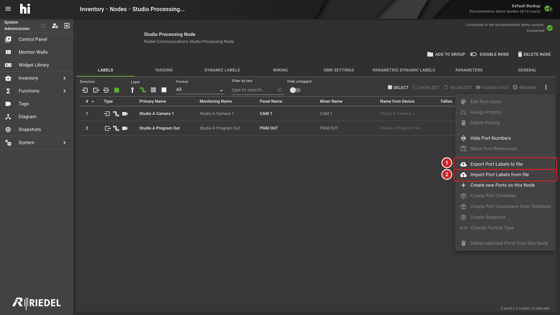
-
Export Port Labels to file downloads the Ports and their labels as an XLSX workbook.
-
Import Port Labels from file applies an edited workbook to the Node.
Export Port Labels to file downloads an XLSX workbook named after the Node, for example Studio Processing Node Ports.xlsx. Its Ports worksheet lists the Ports and their labels. Use it to rename Ports in bulk or to copy names from an existing list.
After you edit the workbook, select Import Port Labels from file and select the edited workbook.
-
hi updates the names and Port numbers of the Ports that the rows identify.
-
hi skips the header row and empty rows.
-
A row that does not match an existing Port can add a new Port when the Node accepts user-created Ports.
-
hi does not delete a Port that is missing from the file.
Information
The import does not remove Ports. To remove Ports, use Delete selected Ports from this Node on a Node type that supports it.
Most Node types define their Ports in the Node template, or read them from the device. Create or delete Ports manually only when Riedel Customer Success instructs you to.
Port Tagging
View and change Tag assignments for Ports. Select one or more Ports and select Assign Tags to modify.
Wiring
The current Wiring tab uses a diagram canvas. It does not provide the older side-by-side table mode.
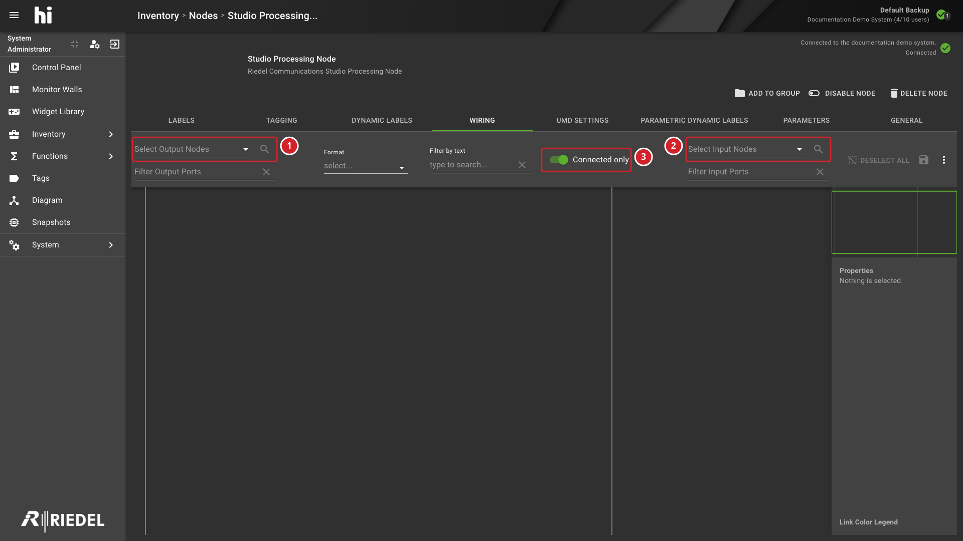
-
Select the output Nodes for the wiring diagram.
-
Select the input Nodes for the wiring diagram.
-
Filter the diagram to show connected paths only.
Use Select Output Nodes and Select Input Nodes to select which devices appear on each side of the current Node. The Port, format, text, and Connected only filters narrow the endpoints shown on the canvas. The minimap and properties sidebar provide navigation and details for the visible diagram.
GPIO Nodes
A GPIO Node, such as a Riedel hiContact, shows Ports instead of Labels, Tagging, and IP. See Riedel hiContact for the device.
The Ports tab lists the GPIO Ports of the Node with these columns: # (when Show Port Numbers is on), Type, Primary Name, Name From Device, and Live Status. The Layer selector is unavailable. Use the direction selector, the Format filter, and Filter by text to narrow the list.
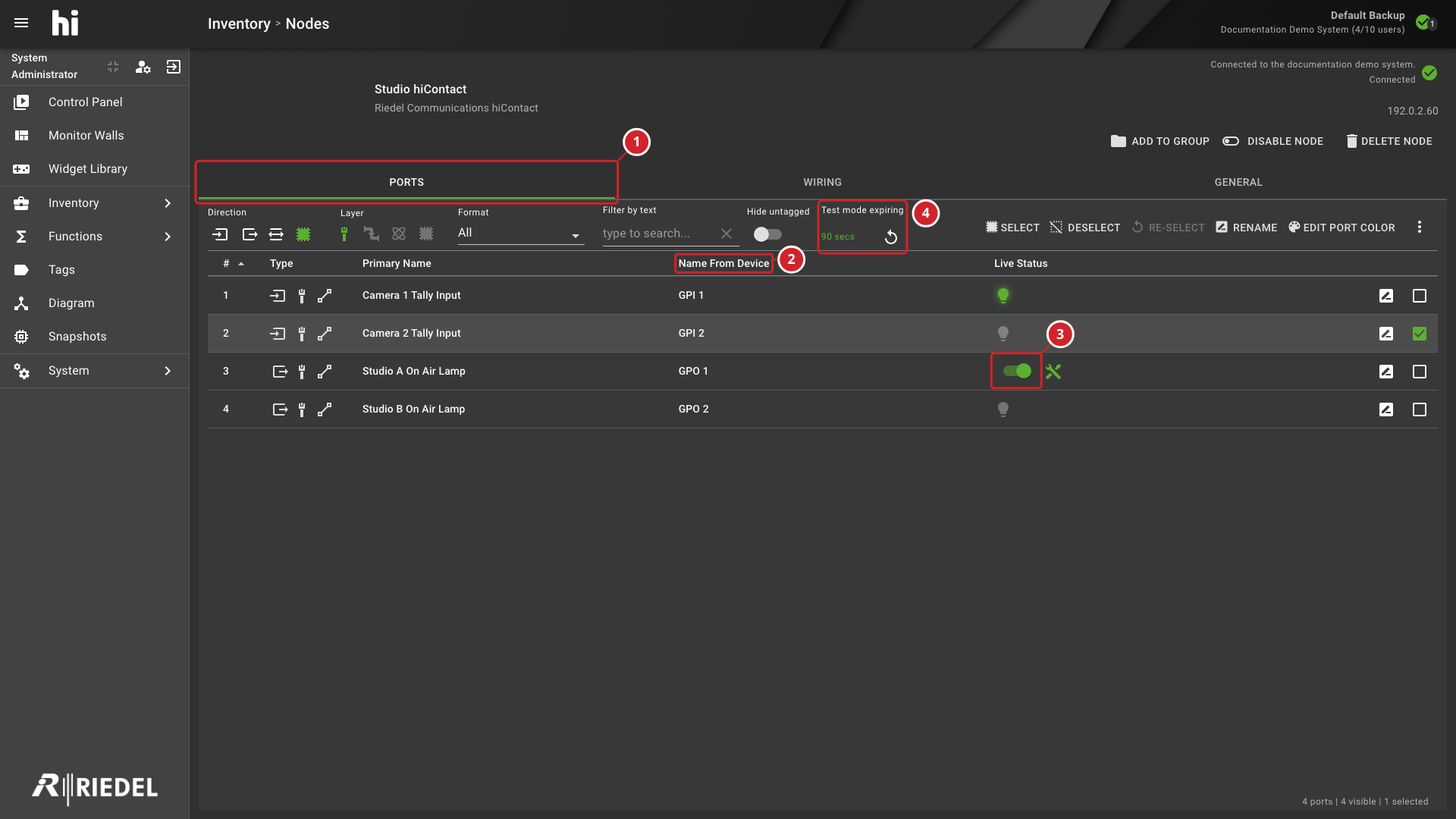
-
The Ports tab, which replaces Labels and Tagging on a GPIO Node.
-
The read-only Name From Device column.
-
The Live Status switch of a Port in test mode.
-
The Test mode expiring countdown and its restart button.
-
Rename a Port - select the Primary Name of a GPIO Port to edit it inline, up to 40 characters. Name From Device is read-only.
-
Live Status - shows the current state of the Port. While a Port is in test mode and the Node is online, Live Status shows a switch instead of the status indicator, and a button with the tooltip Stop testing ends the test mode of that Port.
-
Enable Test Mode, Disable Test Mode, and Force current test states on GPIO ports - available in the three-dot menu for selected GPIO Ports. They are unavailable while no Port is selected or the Node is offline.
-
Test mode expiring - while any Port of the Node is in test mode, the toolbar shows the remaining time in seconds and a button to restart the timer.
The menu of a GPIO Node does not offer Assign Tags, Show Port Numbers, Create Port Container, or Create Snapshot.
IP Tab
The IP tab shows the IP properties of the Ports of a Node. It uses the same Port list and the same three-dot menu as Labels. The Layer selector is not shown. The toolbar offers the direction selector, the Format filter, Filter by text, and the Hide untagged switch.
IP Tab Columns
|
Column |
Content |
|---|---|
|
# |
The Port number. Shown when Show Port Numbers is on. |
|
Type |
The Port type icons. |
|
Primary Name |
The Port name. On a Node with the Node Core capability, the name starts with the name of the owning Node. |
|
Format |
The format of the IP Port. |
|
NIC |
The network interface of each leg. |
|
Source IP |
The Source IP of each leg. |
|
Port (first) |
The Source port of each leg. |
|
Network |
The multicast network of each leg. |
|
Address Range |
The multicast address range of each leg. |
|
Multicast Address |
The multicast address of each leg. |
|
Port (second) |
The multicast port of each leg. |
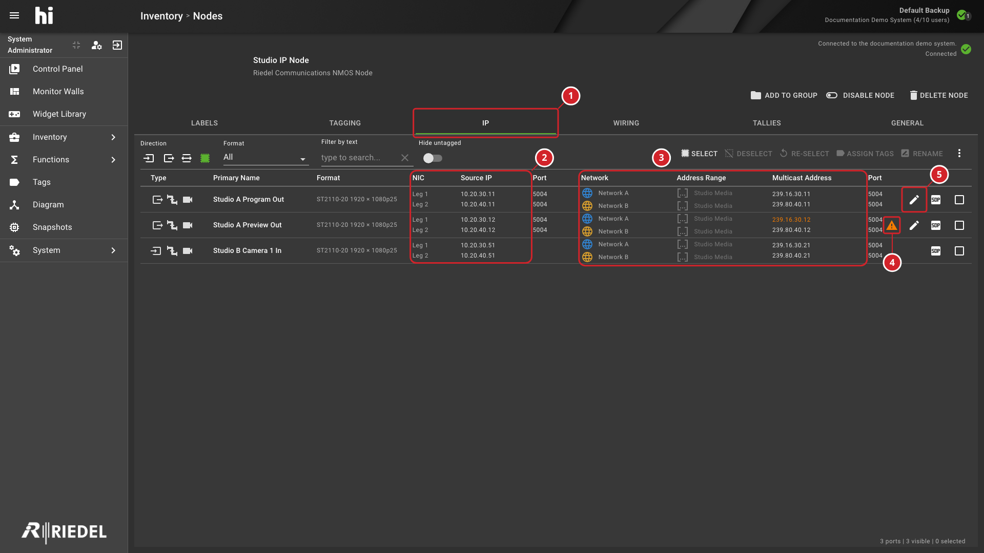
-
The IP tab of the Node.
-
The NIC and Source IP columns, with one line for each leg.
-
The Network, Address Range, and Multicast Address columns, with one line for each leg.
-
The warning icon of a Port whose multicast address conflicts with another Port.
-
The edit icon of an output Port, which opens Edit Multicast Addresses.
Each leg of a Port appears on its own line. At the end of a row:
-
A warning icon marks a Port whose multicast address conflicts with another Port.
-
The edit icon opens Edit Multicast Addresses. It appears only on output Ports that have a multicast address. See Manage Multicast Addresses.
-
The SDP button appears on NMOS Ports.
On the Labels tab, Assign IP resources maps baseband Ports to IP Ports. See Map Baseband Ports to IP Ports.
IP Mapping Tab
The IP mapping tab appears on a baseband Node after you assign IP resources to at least one of its Ports. It lists the mappings of the Node with the columns Type, Destination Port, Linked Device, Source Port, Format, Multicast Address, and Source IP. Use Jump to related IP device to open the IP tab of the linked Node. Select mappings and use Delete to remove them. The tab disappears when the Node has no mapping left.
See Map Baseband Ports to IP Ports for the procedure.
General Options
Available on every Node. Includes Names (Node Name, Short Name, Manufacturer, Product Name) and Operations.
A Node that has a control connection to a physical device provides these Operations:
|
Operation |
Result |
|---|---|
|
Reinitialize |
hi closes all active connections to the device and opens them again. hi repeats the initialization steps, for example it sends all UMD labels of a Multiviewer again. |
|
Reset |
hi terminates and restarts all hi services connected with the device. |
Specific Node types add further Operations, which this page describes with the Node type.
Router Nodes
Router Nodes represent routers and other devices that expose a routing matrix.
Router initialization depends on the integration. hi creates Ports from the configured matrix size or information read from the router, then obtains the supported Crosspoint state. After initialization, hi forwards requested routes to the router. Where supported, hi reads device labels and receives subsequent Crosspoint updates. Use the router's integration page for its discovery, label, and update behavior.
For a Ross Video Ultrix router, choose the routing mode before you create the Node. See Ross Video Ultrix Router.
Router Properties
-
Read labels on startup - when on, hi refreshes the labels from the router database into the hi database each time it connects to the router, for example at system startup. Use it when names in the router change often.
-
Source and destination names (Pro-Bel SW-P-08 integration only) - select which name information from the router database hi uses.
|
Setting |
Description |
|---|---|
|
Input Association Names |
When on, hi reads the Source association names. When off, hi reads the regular Source names. |
|
Input Name Source |
The name field of the router database that hi uses for input names. |
|
Output Name Source |
The name field of the router database that hi uses for output names. |
|
Target |
The name field in hi that receives the selected names. |
Use the Refresh Labels operation on the General tab to copy the names from the router database into hi at any time. The Reinitialize Router operation closes the routing control connection and restarts the initialization.
Direct Routing
Select Routes on the Node detail page to open Direct Routing. The tab appears on Nodes with the Crosspoint Management capability. It is independent of Control Panel Presets and of Port Tags. Use it to change a Crosspoint in a device that you do not expose to users through Tags. Select a Destination and a Source, then select Connect.
Tallies from Router Outputs
On a Node with routing capability, use the Tallies tab to assign a Port of the Node to a Tally. This creates Tally from that Port.
-
Select the + button at the bottom of the tab.
-
Select a Port. Filter the list by entering a name.
-
Under Select Tally, select one of the configured Tallies.
-
Select Assign.
The list of assignments lets you turn each assignment on or off, edit it, or delete it. A Rule can also turn assignments on and off. For example, use a Tally from a router output for an emergency scenario.
Mixer Nodes
Vision mixers report Tally status, for example that input 3 is on air on a program bus. hi needs a mapping from the internal buses of the mixer to the Tallies of the hi system.
hi creates mixer Ports and Tally entries according to the selected integration. Some integrations query the mixer; TSL-based integrations receive configured Tally messages. Use the integration page to confirm the available Ports and Tally mappings.
Mixer Capabilities
-
Tally Provider - every vision mixer provides this capability. It receives Tally updates from the mixer and relays them into hi. Enter the IP address of the mixer. Change the port only when the mixer does not use its factory default.
-
Dynamic Labels - some integrations provide this capability. It changes the labels of mixer inputs using routing and Signal Path information from hi. When it uses the same protocol as the Tally Provider, it needs no extra setup.
Tally Provider via TSL
This section appears only for mixers that send Tally information using TSL. The mixer sends the information and hi receives it, so the IP address of the mixer is not used.
-
In hi, set the incoming port. The default is
31000. The supported range is31000to31999. -
In the configuration of the mixer, enter the IP address of the hi system and the same port.
-
In a redundant installation, enter the virtual IP address of the hi system.
Caution
Use a different incoming port for each Node with an incoming connection. Two Nodes that share a port cannot both receive data.
Use the TSL Settings section to select the Tally Protocol and the transport that the mixer uses to send Tally information. Use the Dynamic Label Settings section to select the Label Protocol and the transport that the mixer uses to receive label information. See Network and Firewall Ports for the network requirements.
Tally Setup
Each entry in the Tally list is a Tally channel of the mixer. The list depends on the mixer model. For example, Grass Valley K-Frame mixers report on-air status for their output buses, such as PGM A and PGM B. Sony mixers report Tally for channels such as GP1_RED and GP1_GREEN. See the manual of the mixer for the meaning of each entry.
To map a mixer Tally to a Tally in hi:
-
Select Edit in the line of the Tally entry.
-
Select a Tally of the hi system.
-
Select the check box to enable the mapping.
Turn a mapping on or off with the switch next to its label. A Rule can also turn a mapping on or off. Use this to build an emergency fallback that disables Tally from one Source and enables it from another. See Manage Rules.
Dynamic Label Setup
The Dynamic Labels tab appears only on devices that can receive label information from a third-party control system. hi creates a Dynamic Label entry for each input Port of the Node. By default, hi traces the start of the Signal Path and sends the name of the Source of Signal Port to the device.
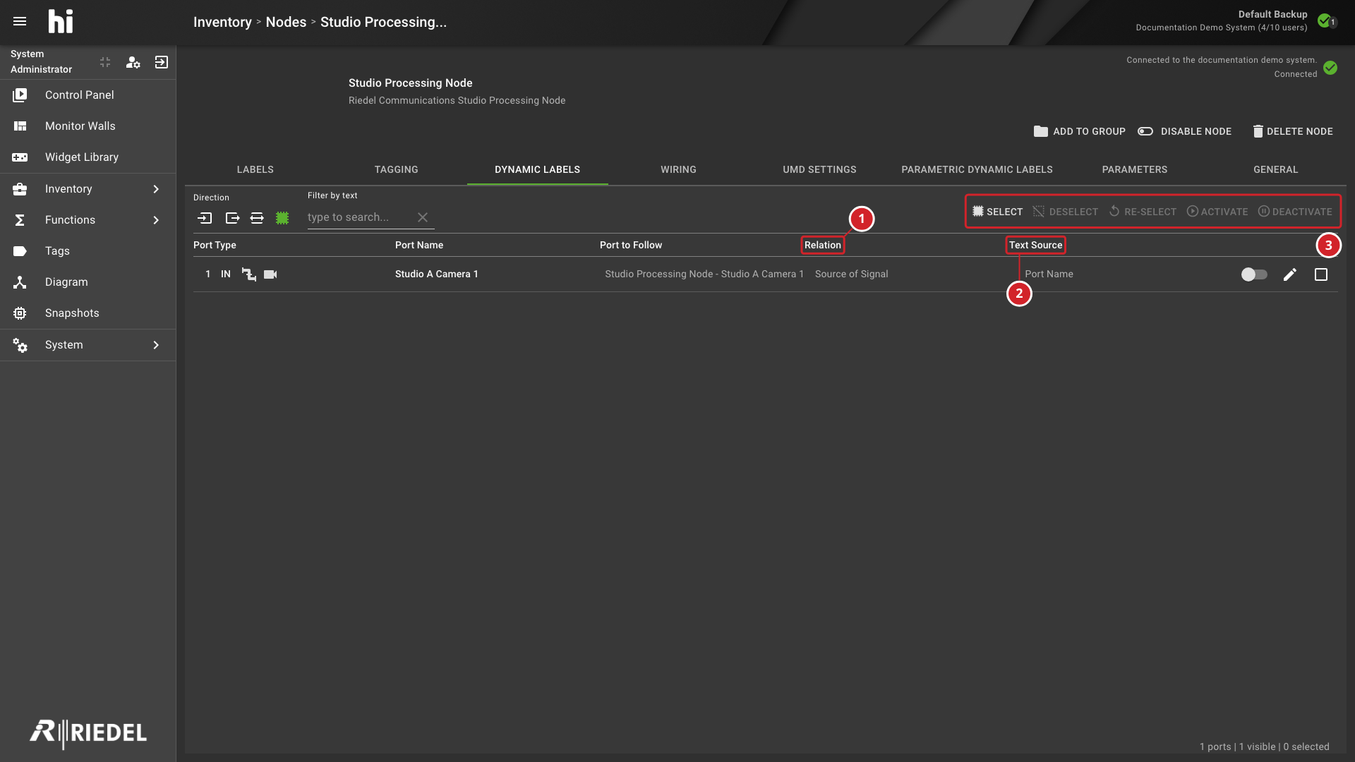
-
Relation shows how the entry finds the Port that its label follows.
-
Text Source shows which name of that Port hi sends as the label.
-
Select, Deselect, Re-select, Activate, and Deactivate act on the selected entries.
By default, hi does not send Dynamic Labels. This prevents hi from overwriting custom names in the device. To start sending labels, select Select to select all entries, then select Activate. Use the switch on a row to turn one entry on or off.
To change how an entry creates its label, select its edit icon. The dialog is titled Edit dynamic label for port and the name of the Port.
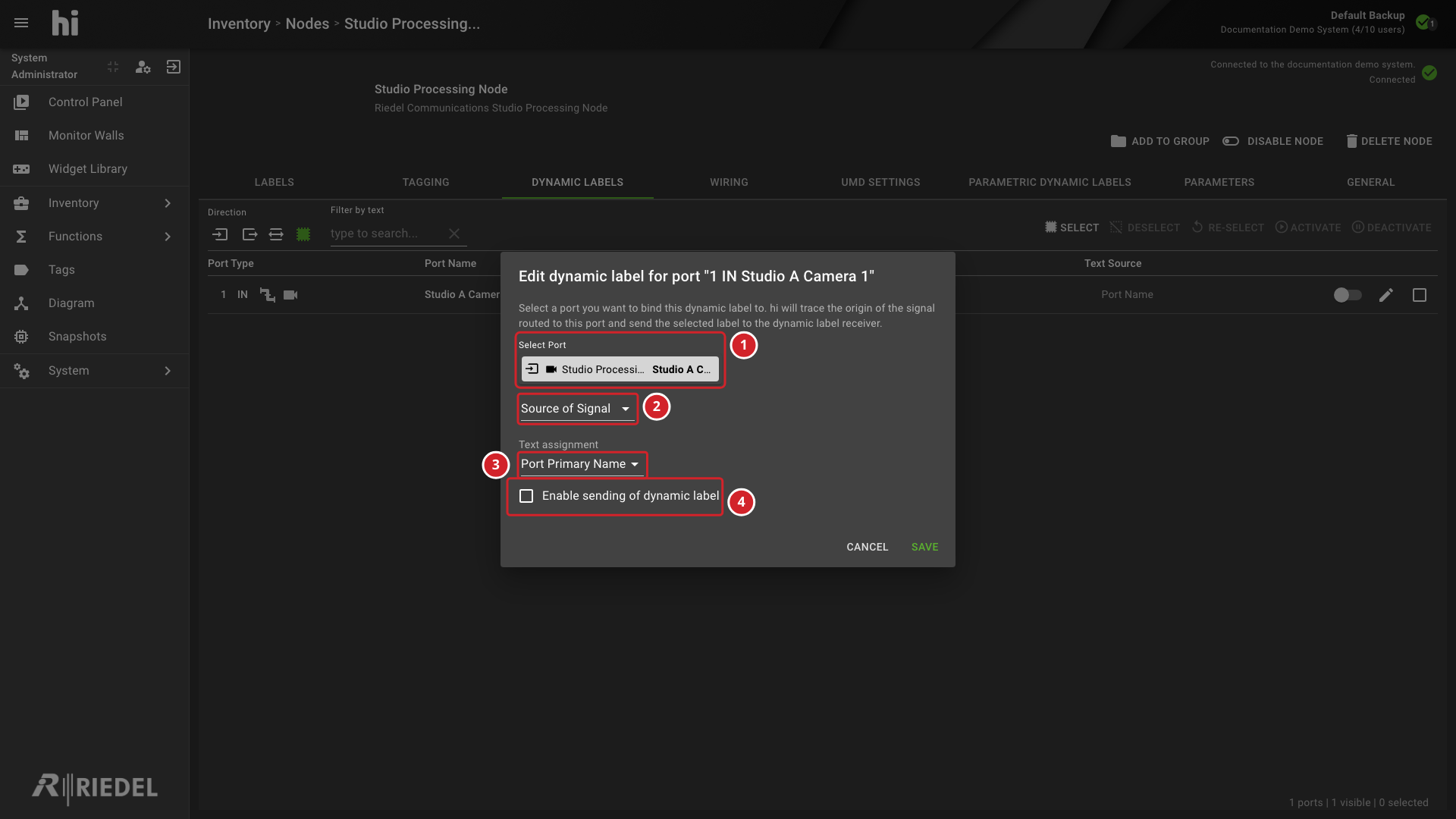
-
Select Port selects the Port that the label follows. This is usually an input Port of the Node.
-
The Relation list selects how the label relates to that Port: Source of Signal, Previous Port, or Selected Port.
-
Text assignment selects which name of the Port hi sends.
-
Enable sending of dynamic label turns the entry on. Select Save to apply the change.
|
Relation |
Label Source |
|---|---|
|
Source of Signal |
The Port at the origin of the Signal Path, for example the camera connected to a CCU. |
|
Selected Port |
The Port that you selected, for example an input of the mixer. |
|
Previous Port |
The Port connected to the selected Port, for example a router output connected to the mixer input. |
The text assignment uses the Port names, the Port Container names, the Node name, or a custom metadata key. See Nodes: Naming for the Port name definitions. Empty Monitoring and Mixer Names inherit as described in Nodes: Naming. For a Port Container name, hi uses the Port Container of the connected Source. If no Port Container is connected to the Destination, hi uses the name of the Flow Port.
Parametric Dynamic Labels
The Parametric Dynamic Labels tab appears on Nodes that expose this capability. The list shows the Parameter, Text Source, and Live State columns.
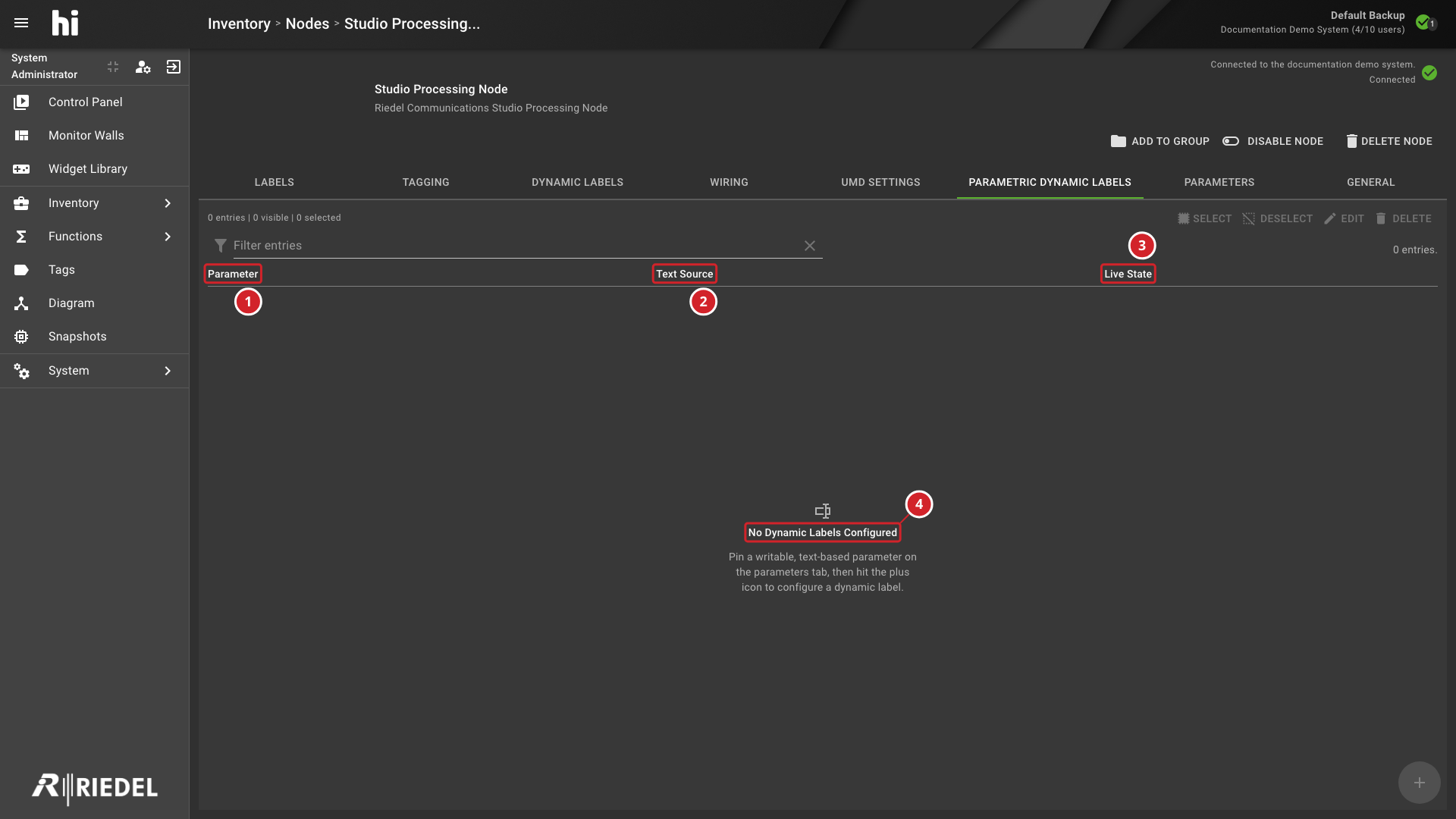
-
Parameter identifies the available Node parameter bindings.
-
Text Source controls the displayed dynamic text.
-
Live State indicates whether the binding is receiving live data.
-
No Dynamic Labels Configured means no bindings have been added yet.
The empty state means that no parametric Dynamic Labels are configured. To create one, first pin a writable text-based parameter on the Parameters tab, then select the + button. Selection and edit actions remain unavailable until an entry exists.
Multiviewer Nodes
See Configure UMD Labels.
When hi starts, it calculates the current label of every configured UMD and sends it to the Multiviewer. After that, hi monitors the Signal Path and sends a new label when a Tally change or a new connection changes it.
Message Properties
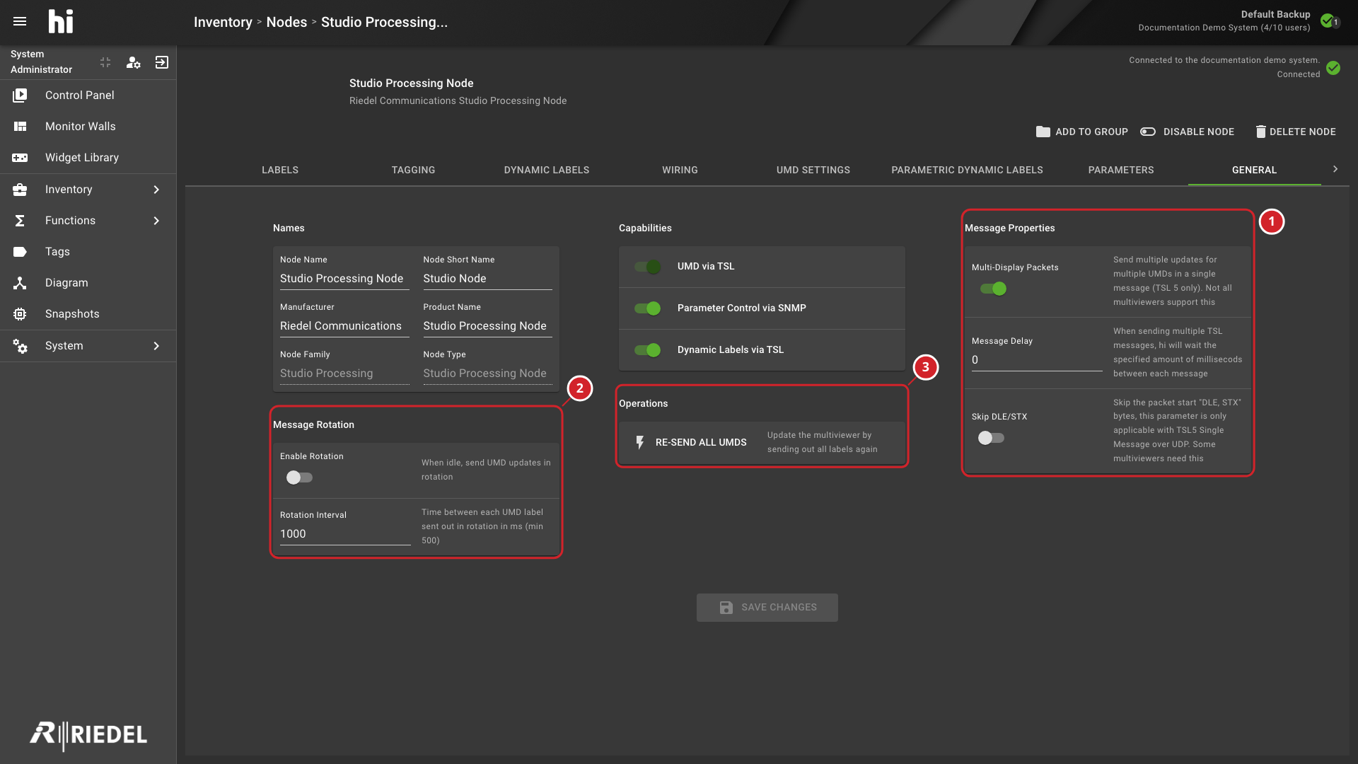
The General tab of a Multiviewer Node shows the message settings in the Message Properties and Message Rotation groups, and the Re-Send all UMDs operation in Operations.
-
Message Properties contains Multi-Display Packets, Message Delay, and Skip DLE/STX.
-
Message Rotation contains Enable Rotation and Rotation Interval.
-
Re-Send all UMDs sends all labels to the Multiviewer again.
|
Setting |
Description |
|---|---|
|
Multi-Display Packets |
When on, hi combines label updates that occur at the same time into multi-display packets. This reduces the number of messages. The connected Multiviewer must support these TSL messages. Turn it off if the Multiviewer does not. |
|
Message Delay |
hi sends label and Tally updates as soon as it calculates them. A delay slows the message stream for Multiviewers that cannot process many messages quickly. A delay also slows updates. For example, a 30 ms delay needs 1.2 seconds to update 40 PIPs after a Tally change. |
|
Skip DLE/STX |
Some Multiviewers implement TSL 5 over UDP differently. Turn this on if the Multiviewer receives no data using TSL 5 over UDP. It has no effect in other configurations. |
Message Rotation
|
Setting |
Description |
|---|---|
|
Enable Rotation |
When on, hi cycles through all configured UMD entries and sends their labels again while no other update occurs. Use it for devices that lose label or Tally information. It increases the number of TSL messages on the network. |
|
Rotation Interval |
The delay in milliseconds between two label updates in idle mode. The minimum value is 500, which sends two updates per second. |
Use the Re-Send all UMDs operation to send the labels of all UMD entries of the Node again, for example after a Multiviewer restarts.
SNMP MIB File Upload
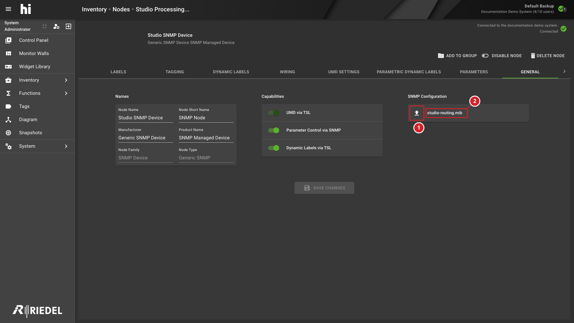
For a Generic SNMP Node, open General and use the MIB Files property to upload one or more .mib files. The imported file names appear beside the upload control. Use MIB files that describe the objects exposed by the connected device; see SNMP Parameter-Controllable Device for the integration requirements and limitations.
-
The MIB upload control on the Node's General tab.
-
An imported MIB file name beside the upload control.
Parameter Control Nodes
Parameter Control Nodes show and monitor the parameters of a device and provide pinned parameters to the hi system. When hi connects to the Node for the first time, it loads the top of the parameter tree through the protocol of the template. Browse the tree and pin the parameters that your workflow needs. After a parameter is pinned, hi keeps its value updated using the integration's supported update mechanism. Use a pinned parameter in several places, for example in a Rule.
|
Operation |
Result |
|---|---|
|
Reinitialize Parameters |
hi closes the connection to the device and restarts the initialization. |
|
Clear Parameter Cache |
hi deletes the local copies of the parameter values in the database and refreshes them from the device. |
See Manage Parameter Containers.
Northbound Nodes
A Northbound Node provides a Pro-Bel SW-P-08 matrix interface for external control systems, such as studio automation. hi starts a SW-P-08 server that acts like a router matrix. Each Northbound Node serves one external system. See Northbound Interface for the protocol behavior, label mapping, and reserved slots, and see the hiDock license details for the license requirement. Each active Northbound session counts against hiLink.
See Northbound Interface: Behavior for supported commands, updates, and unsupported SW-P-08 concepts.
General Settings
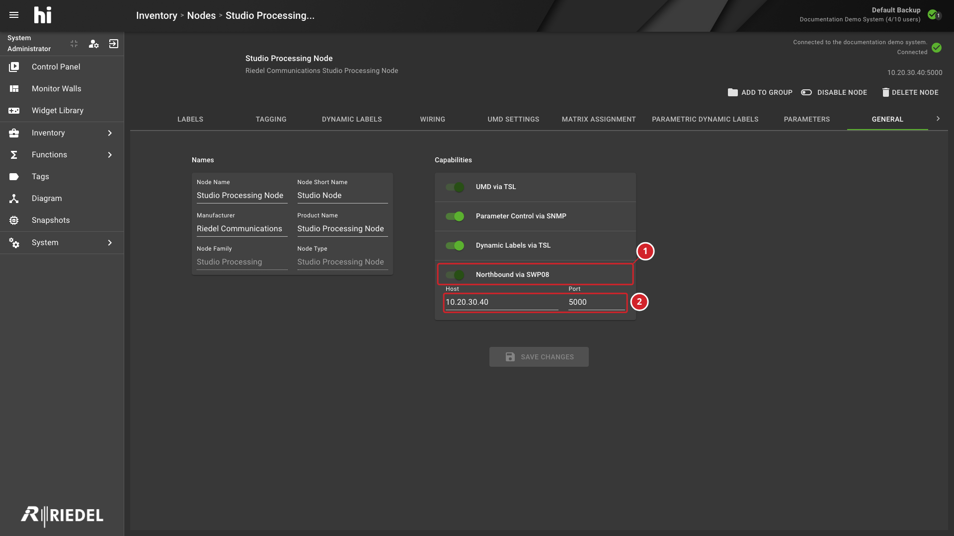
In General, configure the Northbound capability and its protocol properties.
-
Clients - enter up to three IP addresses of the external system.
-
Protocol properties - set the Matrix and Level values. The protocol numbers them from 0, so the first matrix has the value
0. Some applications display it as 1. -
Labels - select which hi label hi reports for each SW-P-08 label length: 4, 8, 12, and 16 characters.
-
Force send crosspoint changed message - on by default; see Behavior.
-
Force Extended Message On Broadcast - off by default. When on, hi always broadcasts Crosspoint changes as extended messages.
Matrix Assignment
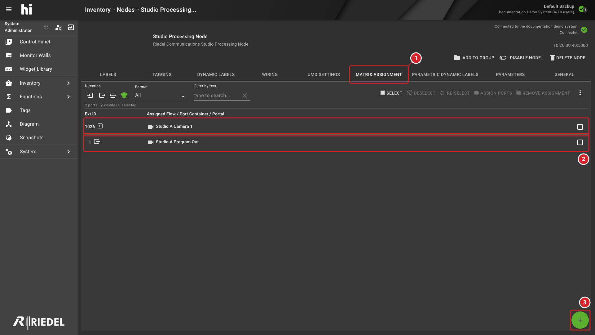
Open Matrix Assignment to assign hi Ports and Port Containers to the slots of the external matrix. A new Northbound Node has no slots.
-
Select the append button at the bottom of the list.
-
Set the number of slots, select Inputs or Outputs, and select Add. Repeat for the other direction.
-
Select a range of input or output slots.
-
Open the assignment menu and select Assign Ports.
-
Select the Sources or Destinations in the Port Picker. Use the filters to find them.
-
Confirm the selection.
Information
Only Ports that have Tags assigned appear in the Port Picker. See Reserved Source Slots for slots that cannot receive assignments.
-
The enabled Northbound capability and its Pro-Bel SW-P-08 protocol.
-
The configured endpoint host and port.
-
The Matrix Assignment tab for the Northbound Node.
-
External slot IDs and their current hi Port assignment state.
-
Append additional matrix slots.
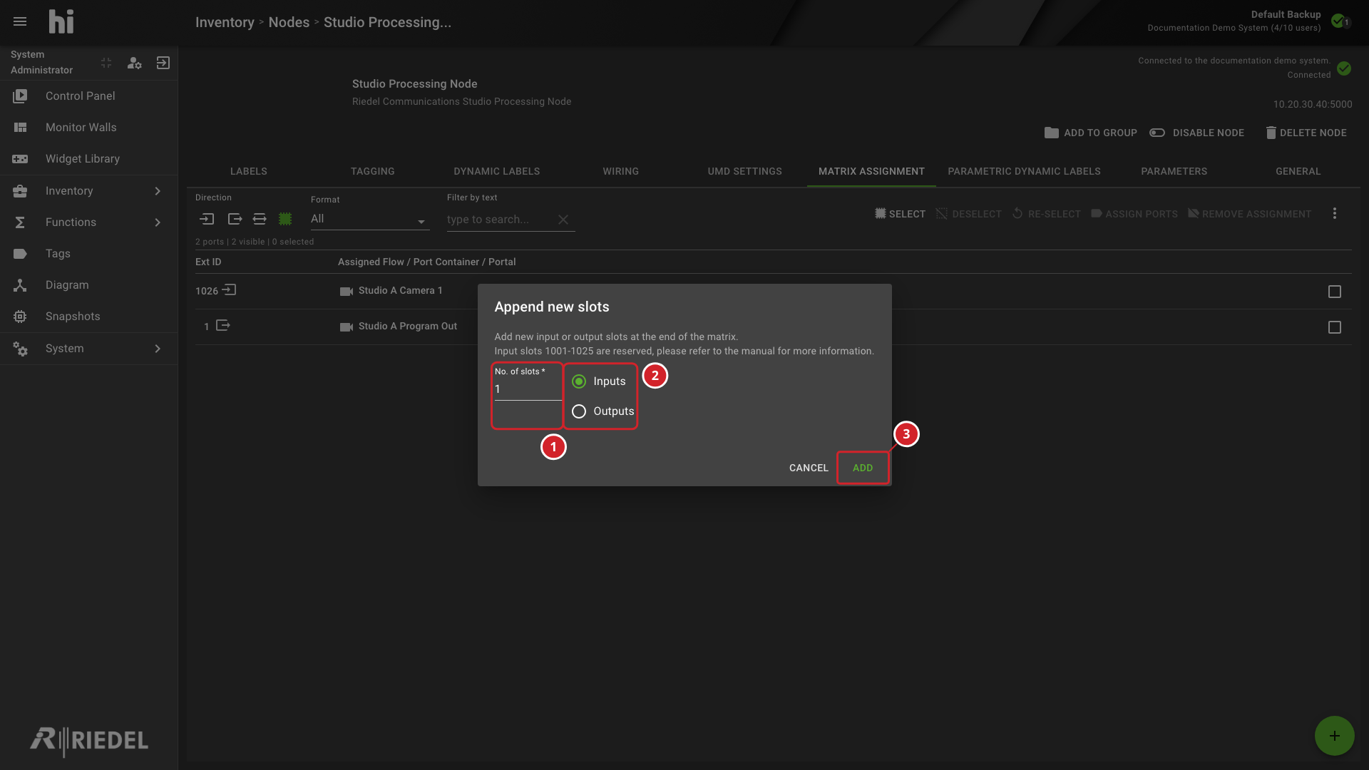
-
Set how many slots to append.
-
Select whether the new slots are Inputs or Outputs.
-
Select Add to append the slots.
Bulk Rename
Verify the Result
After creating or changing a Node, confirm that it appears in the Node List with the expected name, Tags, and Connection State. Verify one supported operation before handing the Node to operators.
Related Procedures
-
Use Assign a Parameter Control to expose a pinned parameter on a Port or Port Container.
-
Use Map Baseband Ports to IP Ports to relate baseband Ports to NMOS IP Ports.
-
Use Manage Multicast Addresses to maintain multicast networks, ranges, and Port addresses.
-
Use View and Edit Topology to verify Wiring and Signal Paths.
-
Use Control Panel to verify routing and Parameter Control.
Task Illustrations
For the procedure, see Configure UMD Labels.
UMD Settings Tab Showing Address, Text Source, Tally Source, Live State, and Row Actions
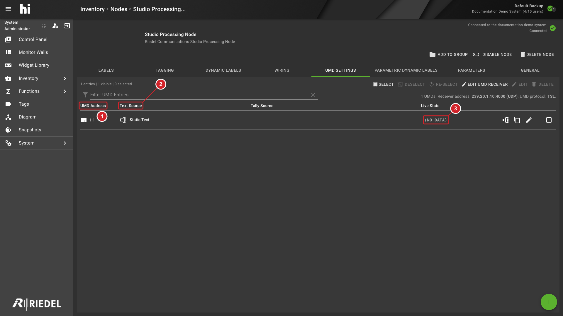
-
UMD Address identifies the configured Screen Id and Display Id.
-
Text Source identifies the source used to populate the UMD.
-
NO DATA indicates that no text is currently available.
Configure UMD Label Dialog Showing Its Address, Text Source, Bound Port, Label Type, and Tally Assignments
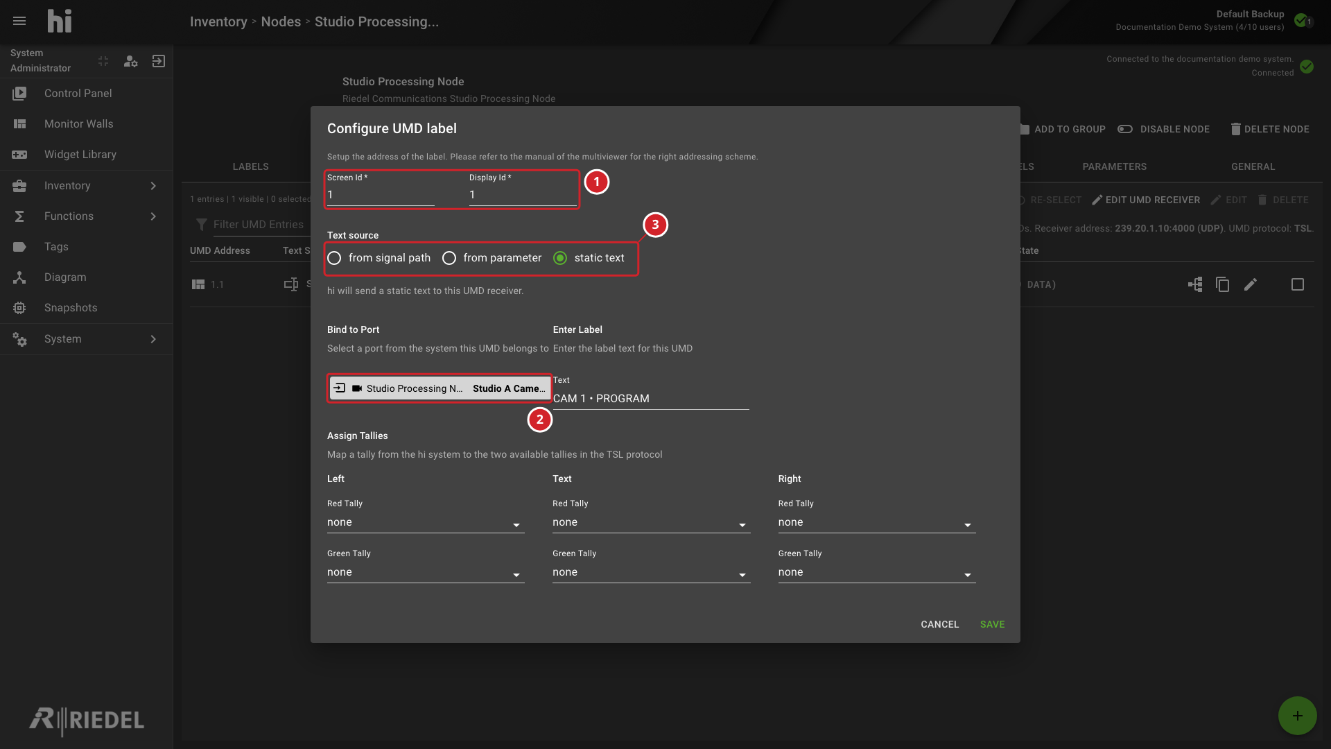
-
Set the UMD Address using Screen Id and Display Id.
-
Bind to Port associates the UMD receiver with a Port.
-
Select the source of text shown by the UMD.
Port Picker in By Node View Showing the Studio Processing Node
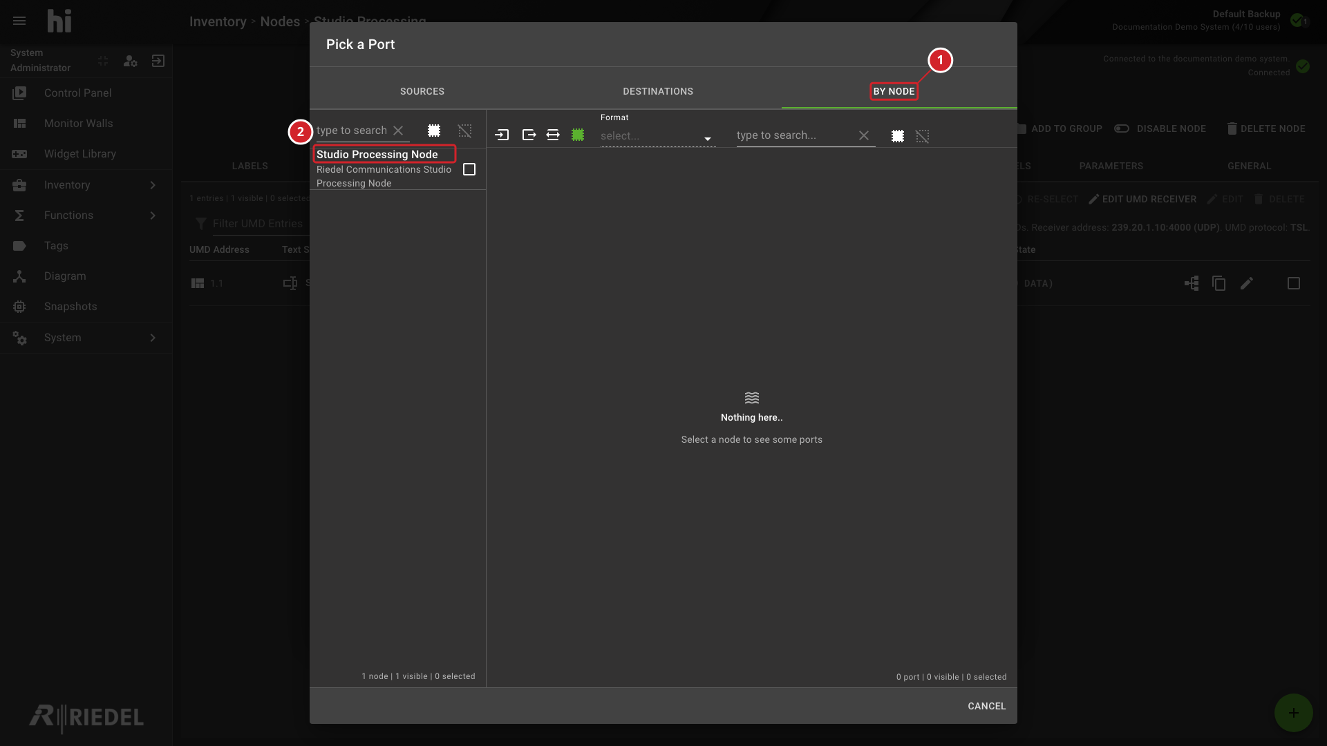
-
By Node displays Ports grouped under their Nodes.
-
Studio Processing Node groups the Ports belonging to this Node.
For the procedure, see Manage Parameter Containers.
Parameter Browser with a device parameter selected and Pin Selected available
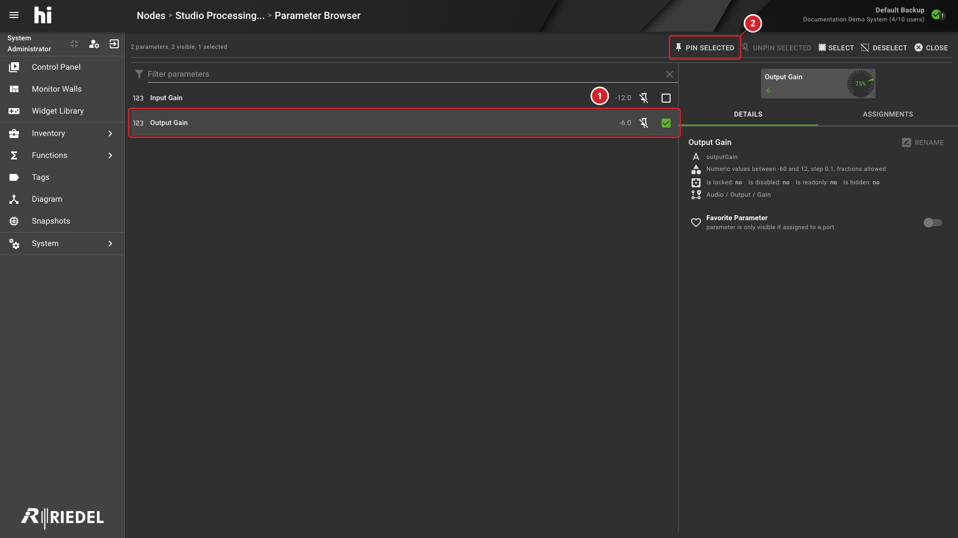
-
The selected parameter from the Node's parameter tree.
-
Pin Selected adds the selected item to the Node's pinned parameter list.
Create Parameter Container dialog for compatible pinned numeric parameters
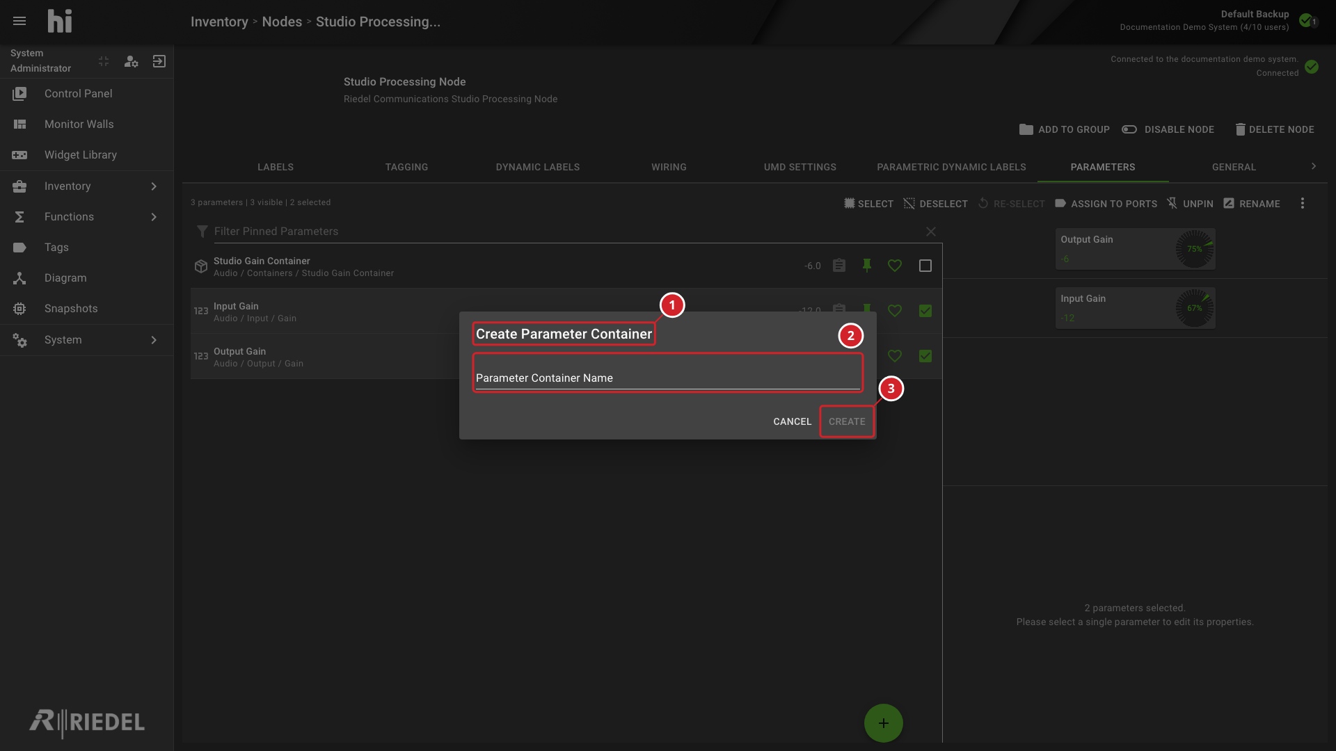
-
The Create Parameter Container dialog.
-
Enter a Parameter Container Name.
-
Select Create to create the Container.
Parameter Container details showing its Contents tab and child parameters
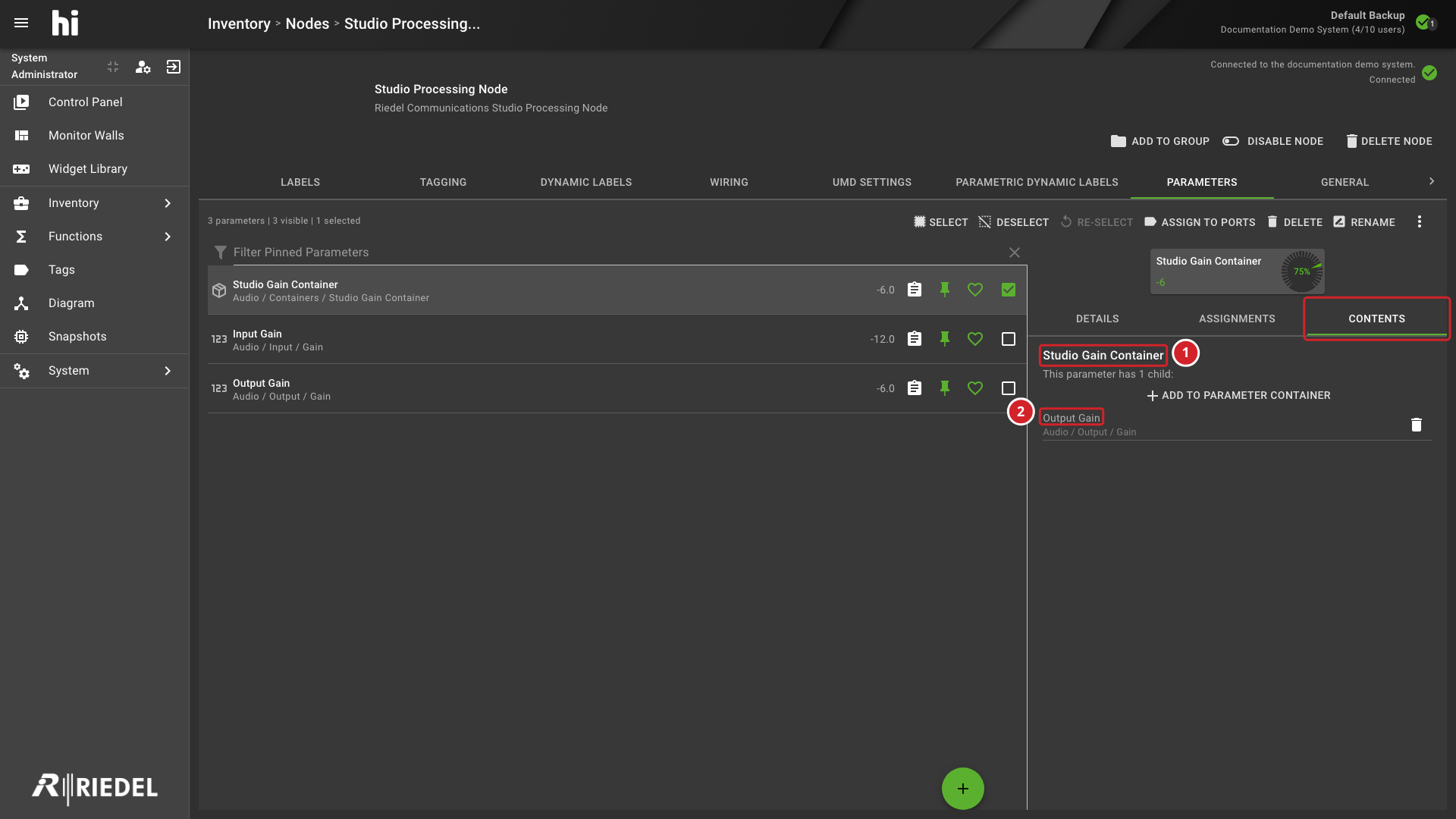
-
The selected Parameter Container and its Contents tab.
-
A pinned Parameter listed as a child of the Container.
Existing Parameter Container and compatible Parameter selected with Add Parameter Container available
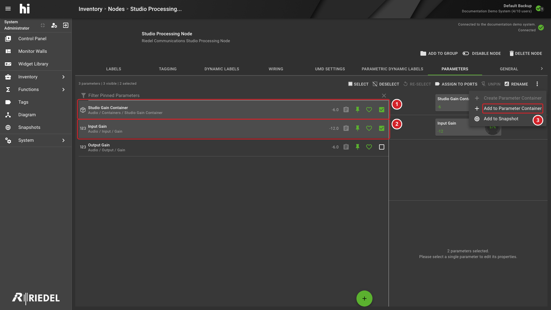
-
Select the existing Parameter Container to receive the additional child.
-
Select a compatible pinned Parameter to add.
-
Add to Parameter Container is available for the compatible selection.
Port Picker opened from Assign to Ports for a pinned parameter
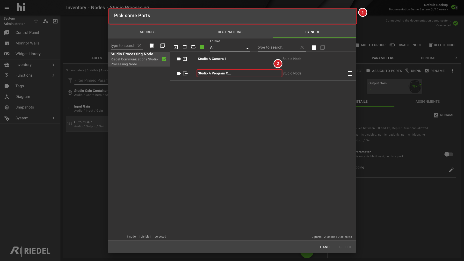
-
The Port Picker opened for parameter assignment.
-
Select the target Port from the available Nodes and Ports.
For the procedure, see Rename Multiple Labels.
Multi-Rename Dialog Showing Rename Mode, Find-and-Replace Fields, Write Targets, and Result Preview
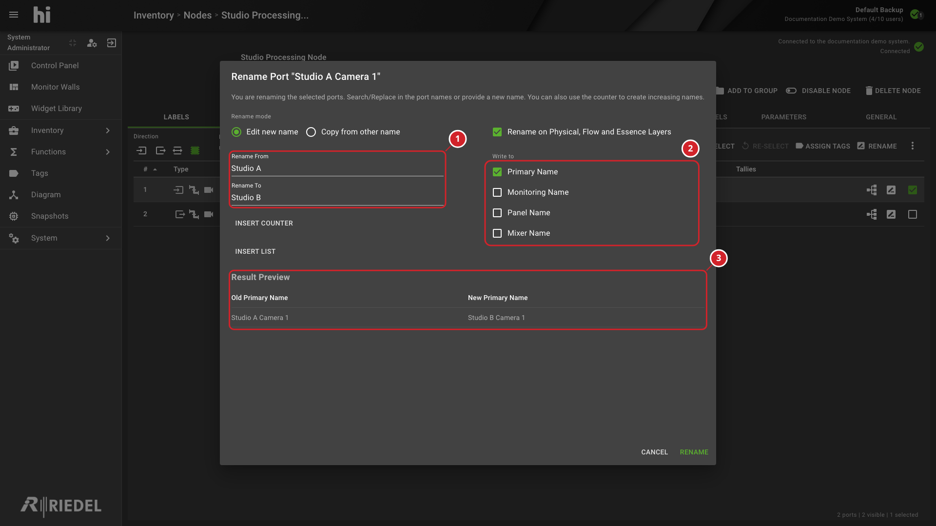
-
Rename From and Rename To define the replacement rule.
-
Write to controls where the new names are applied.
-
Result Preview shows the resulting names before applying the change.